
Owner manual
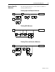
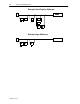
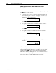
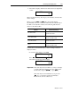
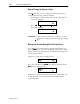
Table Of Contents
- 1747-6.1, Data Table Access Module User Manual
- Important User Information
- Summary of Changes
- Table of Contents
- Preface
- 1 - Data Table Access Module Overview
- 2 - Installation and Power Up
- 3 - Module Setup Procedure
- 4 - Attaching to a Processor
- 5 - Monitoring and Modifying Data
- 6 - Quick Recall Functions
- 7 - Processor Control Functions
- 8 - Message Capability
- 9 - Troubleshooting
- A - Specifications
- B - SLC 500 Data Files and Logical Addressing
- C - Module Display Character Set
- D - Mounting Template
- Index
- Back Cover
Monitoring and Modifying Data 5-11
Publication 1747-6.1
How to Display Different Control Bits Within Elements
With a data file address displayed, you may use the [ ]and[ ]
keys to display different bits within a Timer, Counter, or Control
word, or change bit addresses within a Bit element.
When a Timer, Counter, and Control address is displayed, the [ ]
and [ ]keysworkasfollows:
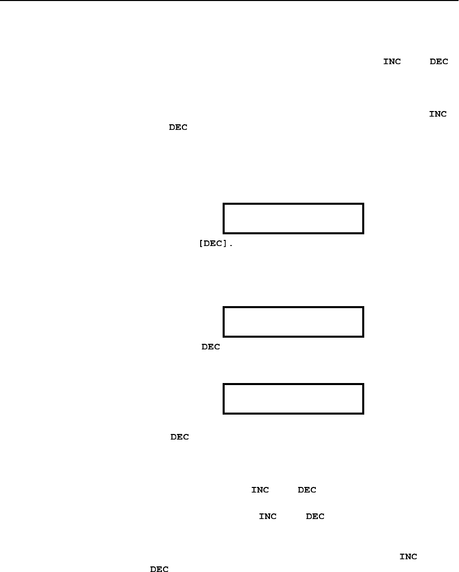
1. To view the Control bits in T4:3, display the address as
previously described. The display shows the highest numbered
Control bit, with the address on the top left and the bit function
and on/off state in the lower right-hand corner:
Press
2. The LCD displays the original bit and the next lower numbered
bit. The bit address in the upper left-hand corner corresponds to
the function and state in the lower right-hand corner:
Press [
].
3. The display shows the next lowest bit in the Control word:
The [ ] key works in the same fashion.
A maximum of three Control bits may be displayed at one time. Only
the Control bit displayed in the lower right-hand corner can be
manipulated. Use the [
]and[ ] keys to access any other bits.
Another function of the [ ]and[ ] keys is to change the Bit
address displayed on the LCD.
When a Bit file address is displayed at the bit level, the [
]and
[ ] keys work as follows:
T4:3.0/15
EN =0
T4:3.0/14
EN=0 TT=0
T4:3.0/13
EN =0 TT = 0 DN = 1