
Owner manual
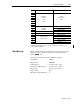
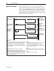
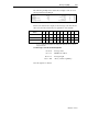
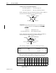
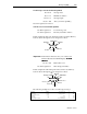
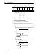
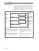
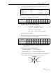
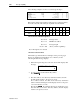
Table Of Contents
- 1747-6.1, Data Table Access Module User Manual
- Important User Information
- Summary of Changes
- Table of Contents
- Preface
- 1 - Data Table Access Module Overview
- 2 - Installation and Power Up
- 3 - Module Setup Procedure
- 4 - Attaching to a Processor
- 5 - Monitoring and Modifying Data
- 6 - Quick Recall Functions
- 7 - Processor Control Functions
- 8 - Message Capability
- 9 - Troubleshooting
- A - Specifications
- B - SLC 500 Data Files and Logical Addressing
- C - Module Display Character Set
- D - Mounting Template
- Index
- Back Cover
Message Capability 8-11
Publication 1747-6.1
To enter the message text into processor memory, refer to your
software user manual.
1-Word Message
This is a clear message. It is enabled by the user program to clear a
displayed message. This message acts the same as pressing the
module key.
The message instruction must be configured as follows:
Read/Write: Write
Target Device: 485 CIF
Control Block: Any Bit or Integer File
Local Source File Address: Any Bit or Integer File
Target Node: Module Node Address
Target Offset: 100
Message Length in Elements: 1
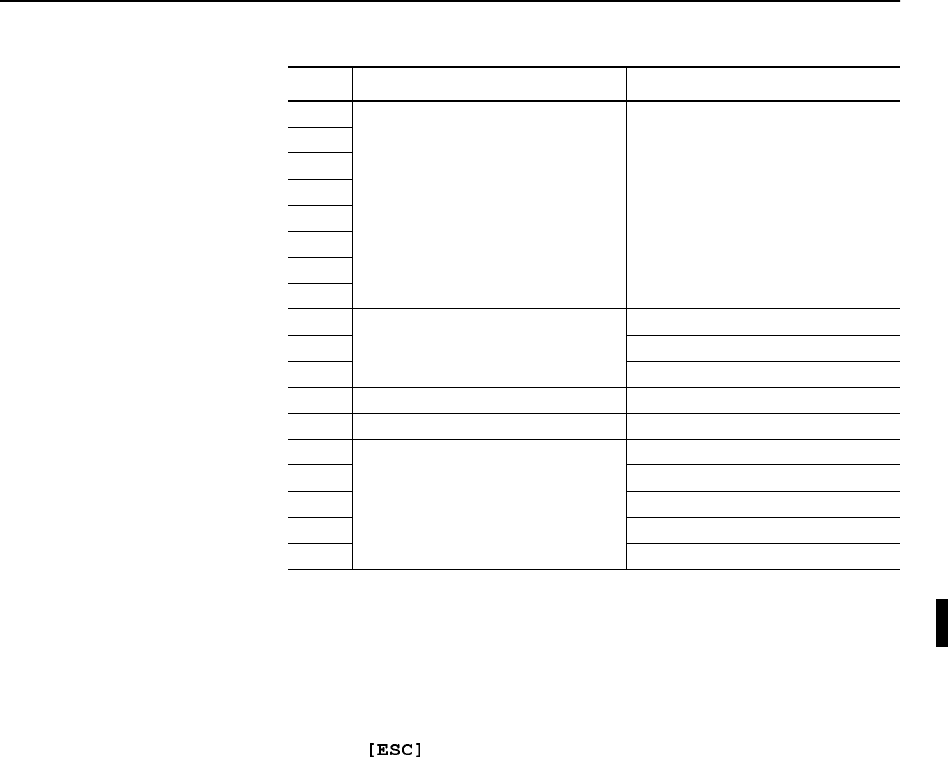
Word Block Description Word Description
0
1
2 16-Character 2 ASCII
3 Message Characters per
4Text Word
5Block
6
7
8 File Type Identifier
9 Data Entry File Number
10 Destination Element Number
11 Address Block Subelement Number
12 Initial Value Word Signed Integer Value
13 File Type Identifier
14 Acknowledge Bit File Number
15 Address Block Element Number
16 Subelement Number
17 Bit Number (0 - 15)