
Owner manual
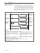
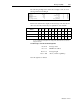
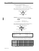
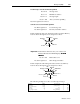
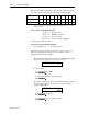
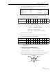
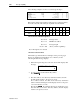
Table Of Contents
- 1747-6.1, Data Table Access Module User Manual
- Important User Information
- Summary of Changes
- Table of Contents
- Preface
- 1 - Data Table Access Module Overview
- 2 - Installation and Power Up
- 3 - Module Setup Procedure
- 4 - Attaching to a Processor
- 5 - Monitoring and Modifying Data
- 6 - Quick Recall Functions
- 7 - Processor Control Functions
- 8 - Message Capability
- 9 - Troubleshooting
- A - Specifications
- B - SLC 500 Data Files and Logical Addressing
- C - Module Display Character Set
- D - Mounting Template
- Index
- Back Cover
Message Capability 8-13
Publication 1747-6.1
The following example is the data monitor display for the 18-word
message instruction in Rung 0:
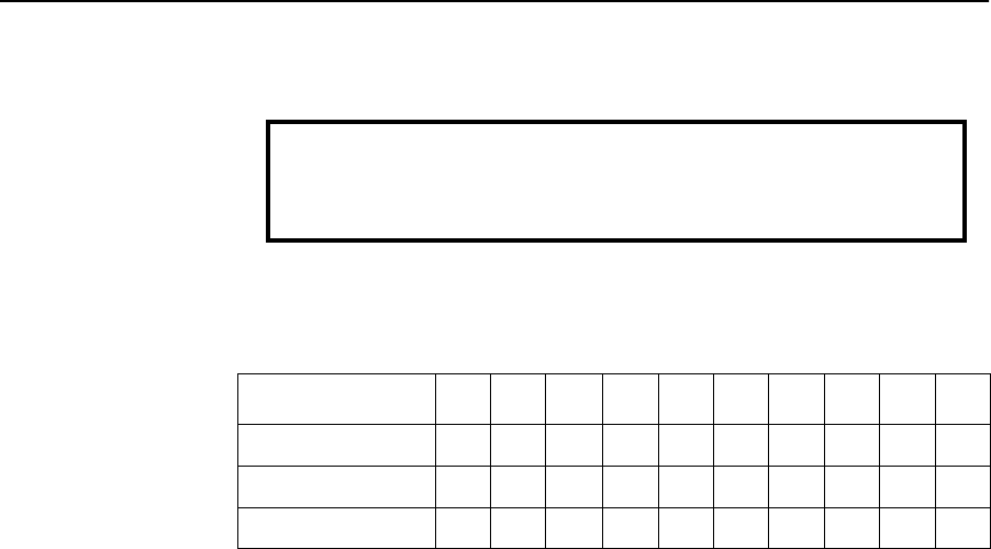
Below is the data monitor display for the message control block and
the local source file, followed by an explanation of the data file.
For ease of viewing, N7:10 through N7:17 are displayed in the ASCII radix. The rest of the file is
displayed in Decimal.
7-word message control block: N7:0 through N7:6
N7:0 = 0 message status
N7:1 = 2 DTAM node address
N7:2 = 18 message length
N7:3 = 100 offset (overwrite capability)
N7:4 through N7:6 = unused
Read/Write:
Target Device:
Control Block:
Local Source File Address:
Target Node:
Target Offset:
Message Length in elements:
WRITE
485 CIF
N7:0
N7:10
2
100
18
ignore if timed out:
to be retried:
awaiting execution:
error:
message done:
message transmitting:
TO
NR
EW
ER
DN
ST
0
0
0
0
0
0
0
Address 0123456789
N7:0 0218100000000
N7:10 E N T E R L O W R A N G E 7 10
N7:20 1013310100