
Owner manual
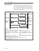
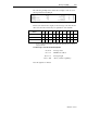
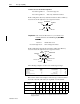
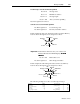
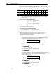
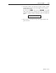
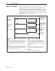
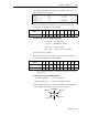
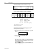
Table Of Contents
- 1747-6.1, Data Table Access Module User Manual
- Important User Information
- Summary of Changes
- Table of Contents
- Preface
- 1 - Data Table Access Module Overview
- 2 - Installation and Power Up
- 3 - Module Setup Procedure
- 4 - Attaching to a Processor
- 5 - Monitoring and Modifying Data
- 6 - Quick Recall Functions
- 7 - Processor Control Functions
- 8 - Message Capability
- 9 - Troubleshooting
- A - Specifications
- B - SLC 500 Data Files and Logical Addressing
- C - Module Display Character Set
- D - Mounting Template
- Index
- Back Cover
8-16 Message Capability
Publication 1747-6.1
Below is the data monitor display for the message control block and
the local source file, followed by an explanation of the data file.
For ease of viewing, N7:60 through N7:67 are displayed in the ASCII radix. The rest of the file is
displayed in Decimal.
7-word control block: N7:60 through N7:66
N7:60 = 0 message status
N7:61 = 2 DTAM node address
N7:62 = 8 message length
N7:63 = 100 offset (overwrite capability)
N7:64 through N7:66 = unused
8-word local source file: N7:70 through N7:77
N7:70 through N7:77 8-word message text
The ladder logic and data monitor examples on the previous pages
must be programmed in SLC 5/02 processor memory for the
following module message display:
1. When the input in rung 0 becomes true, the module displays this
message and the suggested low value to be entered:
2. To enter a value:
• Accept the displayed value:
Press
• Use the numeric keys to change the value:
Press
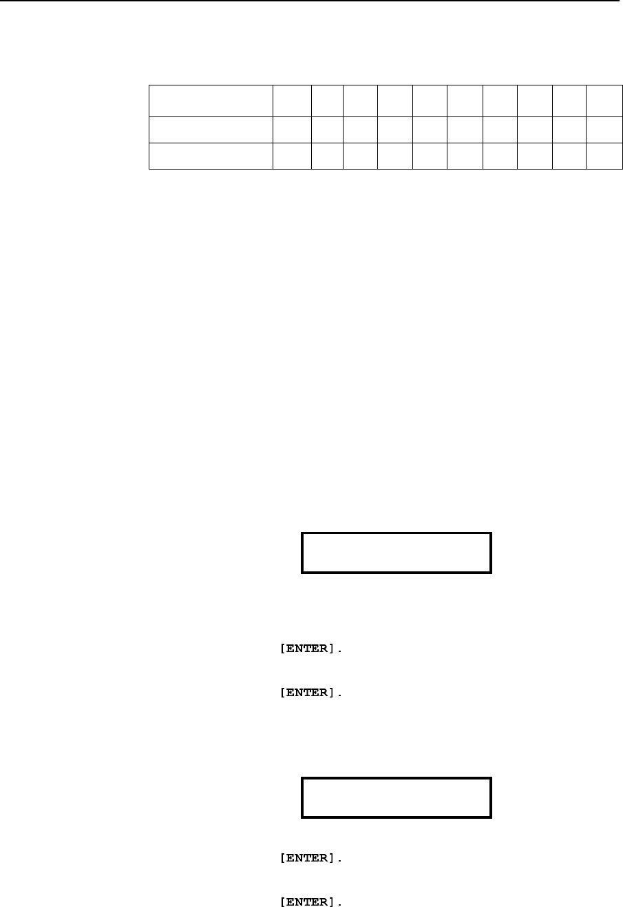
3. The value is written to the data entry destination address, and the
module displays the next message in the sequence, with the
suggested high value:
• Accept the displayed value:
Press
• Use the numeric keys to change the value:
Press
Address 0123456789
N7:60 0 2 8 100 0 0 0 0 0 0
N7:70 N O V A L U E E N T E R E D 0 0
ENTER LOW RANGE
1
ENTER HIGH RANGE
250