
Owner manual
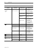
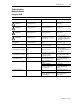
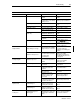
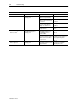
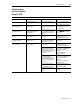
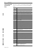

Table Of Contents
- 1747-6.1, Data Table Access Module User Manual
- Important User Information
- Summary of Changes
- Table of Contents
- Preface
- 1 - Data Table Access Module Overview
- 2 - Installation and Power Up
- 3 - Module Setup Procedure
- 4 - Attaching to a Processor
- 5 - Monitoring and Modifying Data
- 6 - Quick Recall Functions
- 7 - Processor Control Functions
- 8 - Message Capability
- 9 - Troubleshooting
- A - Specifications
- B - SLC 500 Data Files and Logical Addressing
- C - Module Display Character Set
- D - Mounting Template
- Index
- Back Cover

9-6 Troubleshooting
Publication 1747-6.1
TROUBLESHOOTING CONSIDERATIONS
GENERAL ERROR SCREEN COMM LED PROBABLE CAUSES RECOMMENDED ACTION
XX is inactive
1
LED illuminated green or
flashing green
The processor at that node
address is not powered up
Power up the processor.
The processor at that node
address is disconnected from
the network
Activate that processor on the
network.
A fault has caused that
processor node addressto
change to a default of one
Change the processor node
address.
The processor is set at the
wrong baud rate
Change the processor baud
rate.
XX is not a CPU
a
LED illuminated green or
flashing green
The node addressyou are
attempting to attach to is a
programming device or
another DTAM
Abort.
A programming device has
been connected to the network
with the same node address
as a processor
Change the node address of
the programming device.
XX not supported
a
LED illuminated green or
flashing green
The node addressyou are
attempting to attach to is a non-
supported device
Abort.
Contact your local Allen-
Bradley sales office.
1. Where XX is the Node Address Value.