
Owner manual
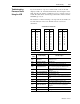
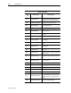
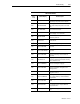
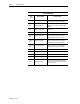
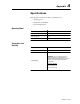
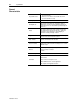
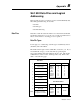
Table Of Contents
- 1747-6.1, Data Table Access Module User Manual
- Important User Information
- Summary of Changes
- Table of Contents
- Preface
- 1 - Data Table Access Module Overview
- 2 - Installation and Power Up
- 3 - Module Setup Procedure
- 4 - Attaching to a Processor
- 5 - Monitoring and Modifying Data
- 6 - Quick Recall Functions
- 7 - Processor Control Functions
- 8 - Message Capability
- 9 - Troubleshooting
- A - Specifications
- B - SLC 500 Data Files and Logical Addressing
- C - Module Display Character Set
- D - Mounting Template
- Index
- Back Cover

A-2 Specifications
Publication 1747-6.1
General
Characteristics
Physical Dimensions
• Front Panel: 152.4 mm H x 139.7 mm W
(6.0inHx5.5inW)
• Back Case: 127.0 mm H x 101.6 mm W x 63.5 mm D
(5.0inHx4.0inWx2.5inD)
Mounting Torques .8 Nm (7.0 in-lb)
Operating Modes
The module can operate in one of two modes, Monitor or
Modify. There is a three position terminal block provided for
mode change. Access to the terminal is provided through the
back case.
Display
The display is liquid crystal, using supertwist nematic fluid.
The display format is 16 characters by 2 lines. A trim pot is
provided for contrast adjustment. LCD backlighting is
provided for viewing in low light conditions.
Keypad
The keypad is of sealed membrane construction. The keys
have an embossed rim and tactile feedback.
Status Indicator
A bi-color LED is provided on the front of the module to
provide communications and fault status.
Interconnect Cable
The standard 1747-C10 cable is used as the interconnector
between the module and a SLC 500 family processor or a DH-
485 link coupler.
Vibration
0.38 mm (0.015 in) peak to peak displacement
2.5 g peak (max) acceleration
1 hr/axis
Noise Immunity Meets NEMA standard ICS 2-230
Certification
UL listed.
CSA certified.
Class I, Division 2, Groups A, B, C, D
Meets NEMA 12 and 13 enclosure applications
CE compliant for all applicable directives