
User guide


Chapter 24
Sequencer Instructions
24–9
Operation
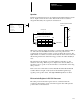
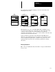
Instruction parameters have been programmed in the SQL instruction shown
below. Input word I:1.0 is the source. Data in this word is loaded into
integer file #N7:30 by the sequencer load instruction.
(EN)
(DN)
SQL
SEQUENCER LOAD
File #N7:30
Source I:1.0
Control R6:4
Length 4
Position 2
0000 0101 0000 1010
07 815
0000 0000 0000 0000
1010 0010 1111 0101
0000 0101 0000 1010
0000 0000 0000 0000
0000 0000 0000 0000
0
1
2
3
4
Step
N7:30
31
32
33
34
Word
00
01
02
03
04
05
06
07
08
09
10
11
12
13
14
15
ON
ON
ON
ON
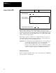
External inputs associated
with I:1.0
Source I:1.0
Sequencer Load File #N7:30
Current Step
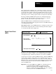
When rung conditions change from false–to–true, the SQL enable bit (EN) is
set. The control element R6:4 increments to the next position in the
sequencer file, and loads the contents of source I:1.0 into this location. The
SQL instruction continues to load the current data into this location each scan
that the rung remains true. When the rung goes false, the enable bit (EN) is
reset.
The instruction loads data into a new file element at each false–to–true
transition of the rung. When step 4 is completed, the done bit (DN) is set.
Operation cycles to position 1 at the next false-to–true transition of the rung
after position 4.
If the source were a file address such as #N7:40, files #N7:40 and #N7:30
would both have a length of 5 (0–4) and would track through the steps
together per the position value. The SQL LENGTH parameter is still 4.
Effect on Index Registers in SLC 5/02 Processors
The value present in the index register S:24 is overwritten when the
sequencer load instruction is true. The index register value will equal the
position value of the instruction.