
User guide


Chapter 1
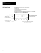
Features, Installation, Powerup
1–11
F1 F2 F3 F4 F5
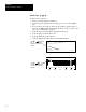
Rack 1 = 1746–A4 4–SLOT RACK
Rack 2 = NONE
Rack 3 = NONE
Slot 0 = 1747–L511 CPU–1K USER MEMORY
Slot 1 = 1746–IA4 4–INPUT 100/120 VAC
Slot 1 = 1746–IA4 4–INPUT 100/120 VAC
The keys scroll
through the I/O module
choices in this display.
Similarly, these keys scroll
through rack and CPU
choices in the appropriate
displays.
CHG NAM CRT FIL EDT FIL DEL FIL MEM MAP >
F1 F2 F3 F4 F5
File Name: Prog Name:2A
File Name Type Size(Instr)
0 System 217
1 Reserved 0
2 Ladder 30
OFL
The keys scroll
through user program
files.
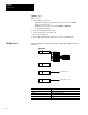
DIAGNSTC ATTACH NODE CFG OWNER
F1 F2 F3 F4 F5
Node Addr. Device Max Addr./Owner
0 APS (31)
1 TERMINAL (31)
*** 2 5/02 (31) ***
3 500–20 (31)
Node Addr: 0 Baud Rate: 19200
OFL
The keys scroll
through active node
addresses.
ADDRESS NEXT FL PREV FL NEXT PG PREV PG
F1 F2 F3 F4 F5
Address 15 data 0
B3:0 0010 0011 0100 1111
B3:1 1000 0010 0000 0000
B3:2 0000 0000 1110 0000
B3:3 0000 0000 0100 0000
B3:4 0101 1101 0100 1000
B3/31 = 1 RUN
The keys
move the cursor left, right,
up and down in a data file
display.