
User guide


Chapter 26
PID Instruction
26–9
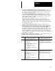
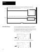
EN DN PV SP LL UL DB TF SC OL CM AM TM
15 14 13 12 11 10 09 08 07 06 05 04 03 02 01 00
PID Sub Error Code (MSbyte)
Setpoint SP
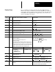
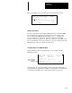
Control Block Layout
Word
0
1
2
Gain K
C
Reset T
i
Rate T
d
Feed Forward Bias
3
4
5
6
*
*
*
*
*
*
7
8
9
10
11
12
Setpoint Max (Smax)
Setpoint Min (Smin)
Deadband
INTERNAL USE DO NOT CHANGE
Output Max %
Output Min %
*
*
*
*
*
13
14
15
16
Loop Update
Scaled Process Variable
Scaled Error SE
Control Output Percent CO (0–100%)
*
17
18
19
20
21
22
INTERNAL USE
DO NOT CHANGE
* You may alter the state of these values with your ladder program.
OL, CM,
AM, TM *
LSW Integral Sum
MSW Integral Sum
ATTENTION: Do not alter the state of any PID control
block value unless you fully understand its function and
related effect on your process.
!
Instruction flags are in the first word of the control block. They include:
• Time mode bit TM (word 0, bit 0) – This bit specifies the PID mode. It
is set when the TIMED mode is in effect. It is cleared when the STI
mode is in effect. This bit can be set or cleared by instructions in your
ladder program.
• Auto/manual bit AM (word 0, bit 1) – This bit specifies automatic
operation when it is cleared and manual operation when it is set. This bit
can be set or cleared by instructions in your ladder program.
• Control mode bit CM (word 0, bit 2) – This bit is cleared if the control
is E=SP–PV (reverse). It is set if the control is E=PV–SP (forward). This
bit can be set or cleared by instructions in your ladder program.
PID Instruction Flags