
User guide


Chapter 4
Data File Organization and Addressing
4–4
Data Files 0 and 1 – Outputs and Inputs
Bits in file 0 are used to represent external outputs. Bits in file 1 are used to
represent external inputs. In most cases, a single 16-bit word in these files
will correspond to a slot location in your controller, with bit numbers
corresponding to input or output terminal numbers. Unused bits of the word
are not available for use.
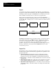
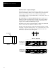
I/O Addressing for a Controller with Fixed I/O: In the figure below, a
fixed I/O controller has 24 inputs and 16 outputs. An expansion rack has
been added. Slot 1 of the rack contains a module having 6 inputs and 6
outputs. Slot 2 contains a module having 8 outputs.
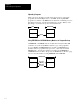
The figure shows how these outputs and inputs are arranged in data files 0
and 1. For these files, the element size is always 1 word.
The table on the following page explains the addressing format for outputs
and inputs. Note that the format specifies
e as the slot number and s as the
word number. When you are dealing with file instructions, refer to the
element as
e.s (slot and word), taken together.
Slot Numbers
Data File 0 – Output Image
0123456789101112131415
X
X
INVALID
INVALID
Slot 0 outputs (0–15)
Slot 1 outputs (0–5)
Slot 2 outputs (0–7)
Data File 1 – Input Image
0123456789101112131415
X
INVALID
INVALID
Slot 0 inputs (0–15)
Slot 0 inputs (16–23)
Slot 1 inputs (0–5)
X
O:0
O:1
O:2
I:0
I:0.1
I:1
0
1
2
24
6
None
16
6
8
Slot Inputs Outputs
I/O I/O I/O
012
Fixed I/O
Controller
Expansion
rack
X
See Addressing “Examples,” next page.X