
User guide


Chapter 4
Data File Organization and Addressing
4–5
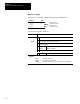
Assign I/O addresses to fixed I/O controllers as shown in the table below:
Format Explanation
O Output
I Input
: Element delimiter
Slot number
(decimal)
fixed I/O controller: 0
O:e.s/b
e
left slot of expansion rack: 1
right slot of expansion rack: 2
I:e.s/b .
Word delimiter. Required only if a word number is necessary as noted
below.
s
Word
number
Required if the number of inputs or outputs exceeds 16 for
the slot. Range: 0 – 255 (range accommodates
multi-word “specialty cards”)
/ Bit delimiter
b
Terminal
number
Inputs: 0 to 15
Outputs: 0 to 15
Examples (applicable to the controller shown on page 4-4):
O:0/4 Controller output 4 (slot 0)
O:2/7 Output 7, slot 2 of the expansion rack
I:1/4 Input 4, slot 1 of the expansion rack
I:0/15 Controller input 15 (slot 0)
I:0.1/7 Controller input 23 (bit 07, word 1 of slot 0)
Word addresses:
O:1 Output word 0, slot 1
I:0 Input word 0, slot 0
I:0.1 Input word 1, slot 0
Default Values: Your programming device will display an address more formally. For example,
when you assign the address I:1/4, the HHT shows it as I1:1.0/4 (Input file, file #, slot 1, word 0,
terminal 4).