
User guide


Chapter 4
Data File Organization and Addressing
4–7
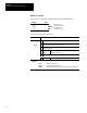
The table below explains the addressing format for outputs and inputs. Note
that the format specifies
e as the slot number and s as the word number.
When you are dealing with file instructions, refer to the element as
e.s (slot
and word), taken together.
Format Explanation
O Output
I Input
: Element delimiter
O:e.s/b e
Slot number
(decimal)
Modular Processor:
Slot 0, adjacent to the power supply in the first rack,
applies to the processor module (CPU). Succeeding slots
are I/O slots, numbered from 1 to a maximum of 30.
I:e.s/b .
Word delimiter. Required only if a word number is necessary as noted
below.
s
Word
number
Required if the number of inputs or outputs exceeds 16 for
the slot. Range: 0 – 31
/ Bit delimiter
b
Terminal
number
Inputs: 0 to 15
Outputs: 0 to 15
Examples (applicable to the controller shown on page 4-6):
O:3/15 Output 15, slot 3
O:5/0 Output 0, slot 5
O:10/11 Output 11, slot 10
I:2.1/3 Input 3, slot 2, word 1
I:7/8 Input 8, slot 7
Word addresses:
O:5 Output word 0, slot 5
O:5.1 Output word 1, slot 5
I:8 Input word 0, slot 8
Default Values: Your programming device will display an address more formally. For example,
when you assign the address O:5/0, the HHT shows it as O0:5.0/0 (Output file, file #, slot 5, word
0, terminal 0).