
User guide


Chapter 4
Data File Organization and Addressing
4–10
Data File 5 – Counters
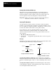
Counters are 3-word elements. Word 0 is the control word, word 1 stores the
preset value, and word 2 stores the accumulated value. This is illustrated
below:
0123456789101112131415
0
1
2
Word
Preset Value PRE
Accumulated Value ACC
Counter Element
Addressable Bits Addressable Words
CU = Count up enable
CD = Count down enable
DN = Done bit
PRE = Preset
ACC = Accum
CU CD DN Internal UseOV UN UA
OV = Overflow bit
UN = Underflow bit
UA = Update accum. value
(HSC in fixed controller only)
Bits labeled “Internal Use” are not addressable.
Assign counter addresses as follows:
Format Explanation
C Counter
Cf:e
f
File number. Number 5 is the default file. A file number between 10 – 255
can be used if additional storage is required.
: Element delimiter
e
Element
number
Ranges from 0 to 255. These are 3-word elements. See
figure above.
Example: C5:0 Element 0, counter file 5.
Address bits and words by using the format Cf:e.s/b
where Cf:e is explained above, and;
. is the word delimiter
s indicates subelement
/ is the bit delimiter
b indicates bit
C5:0/15 Count up enable bit
C5:0/14 Count down enable bit
C5:0/13 Done bit
C5:0/12 Overflow bit
C5:0/11 Underflow bit
C5:0/10 Update accum. bit (HSC in fixed controller only)
C5:0.1 or C5:0.PRE Preset value of the counter
C5:0.2 or C5:0.ACC Accumulated value of the counter
C5:0.1/0 Bit 0 of the preset value
C5:0.2/0 Bit 0 of the accumulated value