
User guide


Chapter 5
Ladder Program Basics
5–10
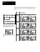
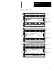
When the state of a bit changes during the scan, the effects this may have in
earlier rungs of the program are not accounted for until the next scan. To
point this out, we have shown successive scans (1000 and 1001, 2000 and
2001, etc.).
The diagram above is the same one that appears on the
preceding page. This diagram is also represented below,
with each instruction replaced with a T or F, indicating
the initial True/False status of the instruction.
The table at the right indicates how the instructions are
executed when XIC instruction I:0/1 changes state.
(I:0/1 represents an external momentary contact push
button.)
TTF F
TTT T
F
T T
T T
TFT F
TFT T
T
T T
T T
FTF F
FTT F
F
F F
F F
Instruction Execution
T = true at time of execution
F = false at time of execution
XIC
I:0/1
Goes
True
Goes
False
Scan 1000 Scan 1001
FFT F
FFT T
T
F F
T T
FTT F
FTT T
T
F F
T T
Scan 2000 Scan 2001
TTT T
TTF F
T
T T
F F
TFF F
TFT F
F
T T
F F
Scan 3000 Scan 3001
FFF F
FFT F
F
F F
F F
FTF F
FTT F
F
F F
F F
Scan 4000 Scan 4001
Goes
False
Goes
True
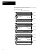
]/[
B3
10
1
] [
I:0.0
1
( )
B3
11
( )
B3
12
2
] [
B3
11
]/[
B3
12
]/[
B3
10
( )
2
( )
B3
10
] [
I:0.0
1
] [
B3
11
3
4
] [
B3
11
] [
I:0.0
1
O:0.0