
User guide


Chapter 5
Ladder Program Basics
5–12
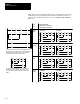
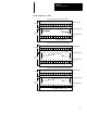
The following figures indicate how the operating cycle works for the 4-rung
ladder program discussed on pages 5–7 through 5–10.
When the Input Goes True
0 0 0 0 0 0 0 0 0 0 0 0 0 0 0 0
15 14 13 12 11 10 9 8 7 6 5 4 3 2 1 0
0 0 0 0 0 0 0 0 0 0 0 0 0 0 0 0
15 14 13 12 11 10 9 8 7 6 5 4 3 2 1 0
2
O:0.0
1
I:0.0
Scan before input goes true (scan 999).
Input Data File
Ladder Program
Output Data File
O:0
I:0
Output Bit De–energized
Input Bit De–energized
Instructions are normal
intensity.
Input Scan
Program
Scan
0 0 0 0 0 0 0 0 0 0 0 0 0 0 1 0
15 14 13 12 11 10 9 8 7 6 5 4 3 2 1 0
0 0 0 0 0 0 0 0 0 0 0 0 1 0 0 0
15 14 13 12 11 10 9 8 7 6 5 4 3 2 1 0
2
O:0.0
1
First scan after input goes true (scan 1000).
Input Data File
Ladder Program
Output Data File
O:0
I:0
Instructions Intensified
Output Bit De–energized
Input bit energized
I:0.0
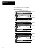
0 0 0 0 0 0 0 0 0 0 0 0 0 0 1 0
15 14 13 12 11 10 9 8 7 6 5 4 3 2 1 0
0 0 0 0 0 0 0 0 0 0 0 0 0 1 0 0
15 14 13 12 11 10 9 8 7 6 5 4 3 2 1 0
2
O:0.0
1
Second scan after input goes true (scan 1001).
Input Data File
O:0
I:0
Output Data File
Ladder Program
Instructions Intensified
Output Bit Energized
Input Bit Energized
I:0.0
Input Scan
Program
Scan
Input Scan
Program
Scan