ControlNet Scanner 1747-SCNR Reference Manual
Important User Information Solid state equipment has operational characteristics differing from those of electromechanical equipment. Safety Guidelines for the Application, Installation, and Maintenance of Solid State Controls (Publication SGI-1.1 available from your local Rockwell Automation sales office or online at http://literature.rockwellautomation.com/) describes some important differences between solid state equipment and hard-wired electromechanical devices.
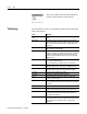
Summary of Changes This publication contains new and revised information not in the last release. New and Revised Information See the table for a summary of the major additions in this manual.
2 Summary of Changes Notes: Publication 1747-RM623D-EN-P - June 2006
Table of Contents Preface What This Manual Contains . . . . . . . . . . . . Who Should Use This Manual . . . . . . . . . . Common Techniques Used in This Manual. Terminology . . . . . . . . . . . . . . . . . . . . . . . Install and Connect the ControlNet Scanner Chapter 1 Prepare to Use the ControlNet Scanner Chapter 2 Configure and Map Scheduled Data Exchange with RSNetWorx for ControlNet Software 3 . . . . . . . . . . . . . . . . . . . . . . . . . . . . . . . . . . . . . . . . . . . . .
Table of Contents 4 Work with the ControlNet Explicit Chapter 4 What This Chapter Contains . . . . . . . . . . . . . . . . . . . . . . . 4-1 Message Instruction Understand the ControlNet Explicit Message Instruction Work with the Explicit Message Instruction (CEM) . . . . . CEM Instruction Parameters . . . . . . . . . . . . . . . . . . . . CEM Instruction Setup Screen Parameters . . . . . . . . . . Troubleshoot . . . . 4-1 4-2 4-2 4-3 Chapter 5 What This Chapter Contains . . . . . . . .
Table of Contents CIP Client Management 5 Appendix C What This Appendix Contains . . . . . . . . . . . . . . . . . . . . . . C-1 What We Assume . . . . . . . . . . . . . . . . . . . . . . . . . . . . . . . C-1 CIP Client Area . . . . . . . . . . . . . . . . . . . . . . . . . . . . . . . . . C-2 Send a Get Attribute All Request to Node 14 Identity Object C-4 SLC 500 Processor: N7 Data File (hex) . . . . . . . . . . . . . C-5 SLC 500 Ladder Program . . . . . . . . . . . . . . . . . . . . . . .
Table of Contents 6 Application Examples Appendix E What This Appendix Contains . . . . . . . . . . . . . . . . . . . . . . E-1 What We Assume . . . . . . . . . . . . . . . . . . . . . . . . . . . . . . . E-1 Example 1: Configure the 1747-SCNR Scanner with the 1746-IV16 Input Module . . . . . . . . . . . . . . . . . . . . . . . . . . E-1 Hardware Setup. . . . . . . . . . . . . . . . . . . . . . . . . . . . . . E-1 Configure the ControlNet Network with RSNetWorx for ControlNet . . . . . . . . . . . . . .
Preface What This Manual Contains Who Should Use This Manual Use this manual to install, configure, and apply the features of the scanner. See the table for a list of where to find specific information. For specification and hazardous locations information, refer to SLC ControlNet Scanner Installation Instructions, publication 1747-IN059.
Preface P-2 The screen captures shown in this manual are pictures of the software’s actual screens. Terminology Publication 1747-RM623D-EN-P - June 2006 See these tables for a list of ControlNet network terms and acronyms used in this manual. Term Definition Actual Packet Interval (API) The measure of how frequently a specific connection produces its data.
Preface P-3 Multicast Connection A connection where one node produces data and multiple nodes consume that exact same data. Connections can be either point-to-point or multicast. Network A series of nodes connected by some type of communication medium. The connection paths between any pair of nodes can include repeaters, routers, and gateways. Network Access Port (NAP) Physical Layer variant that lets a temporary node to be connected to the link by connection to the NAP of a permanent node.
Preface P-4 Publication 1747-RM623D-EN-P - June 2006 Abbreviations and Acronym Meaning API Actual packet interval BNC A connector for coaxial cable having a bayonet-type shell with two small knobs on the female connector which lock into spiral slots in the male connector when it is twisted CIP The control and information protocol defined by part 4 of the ControlNet standard. CIP includes both connected and unconnected messaging.
Chapter 1 Install and Connect the ControlNet Scanner What This Chapter Contains This chapter describes how to install and connect your ControlNet 1747-SCNR scanner. See the table that shows where to find specific information in this chapter.
1-2 Install and Connect the ControlNet Scanner Prepare for Module Installation Before you install your module, you need the following items: Personal Computer with Microsoft Windows SLC 1746 Chassis with SLC 5/02, 5/03, 5/04, or 5/05 Processor and Appropriate Programming Software (RSLogix 500 Software) RSNetWorx for ControlNet software, Catalog Number 9357-CNETL3 1747-SCNR Scanner Reference Manual, Publication 1747-RM623 (this manual) ControlNet 1784-PCC (shown), or 1784-PCIC, or 1784-KTCX15, or 177
Install and Connect the ControlNet Scanner Select the ControlNet Node Address 1-3 Select the ControlNet node address of the 1747-SCNR module by setting the two 10-digit rotary switches on the top of the scanner. 10-digit Rotary Switch: Ones Digit 10-digit Rotary Switch: Tens Digit Top View of Module 30752 You can select a node address from 01 to 99 for a device on a ControlNet link. Zero (00) is not a valid node address.
1-4 Install and Connect the ControlNet Scanner Insert the 1747-SCNR Scanner Into the Chassis To insert the 1747-SCNR scanner into the SLC chassis complete these procedures. ATTENTION Do not install the 1747-SCNR scanner with the chassis power supply on. Installing the module with the chassis power supply on may damage the module. 1 . Turn off the SLC chassis power supply. IMPORTANT If you disconnect the ac power, you lose the chassis ground. Electrostatic damage (ESD) protection is lost. 2.
Install and Connect the ControlNet Scanner 1-5 3. Insert the module into the slot you have selected, noting that we recommend that you insert the 1747-SCNR scanner as close to the chassis power supply as possible. 4. Apply firm and even pressure to seat the module in the I/O chassis backplane connectors. 5. Restore power to the SLC chassis. Connect to a ControlNet Network Connect the 1747-SCNR scanner to a ControlNet network via a tap with a 1 m (39.4 in.) drop cable.
1-6 Install and Connect the ControlNet Scanner Nonredundant Media Redundant Media A A B 30802 Remove the tap’s dust cap—located on the straight or right-angle connector—and set it aside. . If Your Network Supports Nonredundant media Redundant media (1) Connect the Tap’s Straight or Right-angle Connector To the channel A connector on the scanner—channel B is not used.
Install and Connect the ControlNet Scanner 1-7 Connect Programming Terminal to a ControlNet Network You can connect the programming terminal to a ControlNet network through a: • ControlNet product NAP using a network access cable (1786-CP). • tap on a ControlNet network. ATTENTION Do not connect the same communication card to both the NAP and a tap on the ControlNet network.
1-8 Install and Connect the ControlNet Scanner ATTENTION SLC 500 I/O Configuration for the 1747-SCNR Module Use the 1786-CP cable when connecting a scanner to the network through a NAP. Using a commercially-available RJ-style cable could result in network failure. Select the I/O card. If you do not have an I/O card, complete the following procedure. Open RSLogix 500 software and use the following procedure to configure the 1747-SCNR module. In the RSLogix 500 project Window: 1 .
Chapter 2 Prepare to Use the ControlNet Scanner What This Chapter Contains Read this chapter to understand how to use your ControlNet 1747-SCNR Scanner. The following table describes what this chapter contains and where to find specific information.
2-2 Prepare to Use the ControlNet Scanner Communicating with Your SLC processor Using M1 and M0 Files Your processor can communicate with the scanner via M1 file transfer reads and M0 file transfer writes. The scanner does not send data to your processor. Data transfer between your scanner and the processor must be initiated by the processor. For example, data is sent, or written, to the scanner by your processor by placing the data in the M0 file.
Prepare to Use the ControlNet Scanner The ControlNet system is designed to do this: • Provide high-speed, repeatable, deterministic I/O transmission. • Let control and message information co-exist on the same physical media. • Make sure that I/O data transfers are not affected by: • programming-terminal activity. • inter-scanner message activity on the network. Scheduled Data Transfer Operations on a ControlNet Network ControlNet scheduled data transfer on a 1747-SCNR Scanner: • is continuous.
2-4 Prepare to Use the ControlNet Scanner Unscheduled Data Transfer Operations on a ControlNet Network The ControlNet network lets you use unscheduled messaging in addition to deterministic delivery. Unscheduled operations include: • • • • peer-to-peer messaging. messaging from any remote CIP client device. messaging from programming devices. CIP client message initiated by the SLC processor ladder program. This process is illustrated in the figure.
Prepare to Use the ControlNet Scanner 2-5 The ControlNet system places your scheduled transfers in the first part of each network update interval (NUI). Time is automatically reserved for network maintenance, and unscheduled transfers are performed during the remainder of the interval. Unscheduled messaging on a ControlNet network is non-deterministic.Your application and your configuration (for example, number of nodes, application program, NUT) determine how much time there is for unscheduled messaging.
2-6 Prepare to Use the ControlNet Scanner Module Status (I:e.0) Bit 0 1747-SCNR Module Faulted. Bit 1 1747-SCNR Communication Module Fault The 1747-SCNR scanner is not on line. See M1 word 2 (M1:e2) for the ControlNet network status. Bit 2 1747-SCNR Connection Fault There is a fault in at least one scheduled connection. Bit 3-7 Reserved.
Prepare to Use the ControlNet Scanner 2-7 Module Status (M1:e.1) See Troubleshooting for probable causes and recommended actions. Value Description 0x20 The scanner is not configured. 0x21 The current configuration is not valid. 0x22 Connections are configured, but no connections are established. 0x23 Connections are configured, but only 25% are successfully established. 0x24 Connections are configured, but only 50% are successfully established.
2-8 Prepare to Use the ControlNet Scanner Discrete Output File Word Offsets 0 Word ControlNet Size Transfer Mode 1 N/A 1-31 31 Scheduled Contents Description Module Command Bit field used to send commands to the 1747-SCNR Scanner. ControlNet Output You can map up to 31 words of Data output data using RSNetWorx for ControlNet software. Module Command (O:e.
Prepare to Use the ControlNet Scanner 2-9 1747-SCNR M0 File Word Offsets 0-2 3-255 Word Size 3 253 ControlNet Contents Transfer Mode N/A Reserved Scheduled ControlNet Output Data 256-699 700-955 444 256 N/A Unscheduled Reserved Local Database 1000-1650 651 Unscheduled CIP Client Message Area Description Reserved. Using the RSNetWorx for ControlNet software, you can map scheduled output data in this area. Reserved.
2-10 Prepare to Use the ControlNet Scanner All scheduled data transfer to Input, Output, M0 and M1 files must be mapped on a ControlNet network. You have to specify where I/O data is to be read from or written to, in other words, mapped. Data size and location within 1747-SCNR data files have to be configured for each connection you want to setup with a remote device. The configuration is performed using RSNetWorx for ControlNet software.
Prepare to Use the ControlNet Scanner 2-11 CIP Client Request Transfer The scanner provides some limited CIP client messaging capability. Using ladder programming, you can manually build a message request for up to approximately 240 words of in and approximately 240 words of out data, to let configuration and other limited messaging to remote devices. The CIP client message management is detailed in CIP Client Management.
2-12 Prepare to Use the ControlNet Scanner Notes: Publication 1747-RM623D-EN-P - June 2006
Chapter 3 Configure and Map Scheduled Data Exchange with RSNetWorx for ControlNet Software What This Chapter Contains This chapter provides information about the mapping of scheduled connections between 1747-SCNR remote devices. This chapter also contains questions you should ask before configuring your 1747-SCNR scanner. The following table describes what this chapter contains and its location.
3-2 Configure and Map Scheduled Data Exchange with RSNetWorx for ControlNet Software Data Transfer Mapping You can use the configuration software (RSNetWorx for ControlNet software) to select either Input or M1 files for input data and either Output or M0 files for output data. However, it is more appropriate to use Input and Output files for critical I/O data transfer and M1 and M0 for non-critical I/O data transfer. Input and Output files contain 31 words each.
Chapter 4 Work with the ControlNet Explicit Message Instruction What This Chapter Contains The following table describes what this chapter contains.
4-2 Work with the ControlNet Explicit Message Instruction The CEM instruction uses an integer control block for storing the instruction parameters and a configuration setup screen, similar to the MSG instruction. The CIP commands consist of a Service Code; the object Class, Instance, and Attribute; and Send and Receive Data (if required for the selected Service Code). The setup screen provides a list of standard CIP Services to select from, including: • • • • • • Read Assembly. Write Assembly.
Work with the ControlNet Explicit Message Instruction 4-3 CEM Instruction Parameters Enter the following parameters when programming this instruction. • Control Block is an integer file address that you select. It is a block of words, containing the status bits and other data associated with the CEM instruction. • Control Block Length is a display-only field that indicates how many integer file words are being used by the control block. For the CEM instruction, the length is always 67 words.
4-4 Work with the ControlNet Explicit Message Instruction • Data Table Address (Send Data) If Size in Words (Send Data) is non-zero, then this field requires a starting integer (N) file address for storing the Send Data. • Data Table Address (Receive Data) If Size in Words (Receive Data) is non-zero, then this field requires a starting integer (N) file address for storing the Receive Data. Parameters for target device on the general tab include the following.
Work with the ControlNet Explicit Message Instruction 4-5 • Service Code (hex) This field is read-only unless the Custom Service is selected. Possible Service Codes are 1 to 7F (hex). See Volume 1 of the CIP Common Specification, Appendix A, for the list of valid explicit messaging Service Codes. • Class (hex)/(dec) Possible Classes are 0 to FF (hex). See Volume 1 of the CIP Common Specification for the list of defined Classes.
4-6 Work with the ControlNet Explicit Message Instruction Definitions for Message Status Bits on the General Tab See the table that lists the various status bits associated with the CEM instruction as displayed in the CEM instruction setup screen.
Work with the ControlNet Explicit Message Instruction 4-7 Scanner Status, Error, and Error Description on the General Tab The Scanner Code displays the explicit message status returned by the scanner. A scanner code of 0 means no errors. See the CEM Instruction Scanner Codes table for a list of other valid scanner codes.
4-8 Work with the ControlNet Explicit Message Instruction A scanner code of 0x207 results in an error code of 1. All other scanner codes listed result in an error code of 2. The Valid CEM Instruction error codes table lists all valid CEM instruction error codes. Valid CEM Instruction Error Codes Error Code Description of Error Condition 0 No error. 1 Timeout error. ControlNet explicit message timed out by scanner. 2 Scanner error. See Scanner Status. 3 Configuration error.
Work with the ControlNet Explicit Message Instruction 4-9 Send Data Tab The Send Data Tab provides a convenient way of viewing and entering in data to be sent along with the explicit message command. The data is shown in byte format with a selectable radix of either Decimal or Hex/BCD. The display only shows the number of words that are defined in the Size in Words (Send Data) field, starting with the low byte of the first word as defined in the Data Table Address (Send Data) field.
4-10 Work with the ControlNet Explicit Message Instruction Control Block Layout See this table for the control block layout.
Chapter 5 Troubleshoot What This Chapter Contains The following table describes what this chapter contains and its location. For Information About Troubleshooting Apply chassis power Alphanumeric display OK indicator and display mnemonics Troubleshoot with the Status Indicators and Status Display See Page 4-1 4-2 4-2 4-3 The 1747-SCNR module has indicators on the front plate, as shown in the figure.
5-2 Troubleshoot Apply Chassis Power When you apply chassis power, the module address and status display cycles through the following mnemonics: 1 . POST - The 1747-SCNR runs Power On Self Test. 2. 1 1 1 1 , 2222, etc. - The 1747-SCNR is executing its startup sequence. 3. The 1747-SCNR firmware version is displayed temporarily after startup. 4.
Troubleshoot OK Indicator and Display Mnemonics Sequence OK Alpanumeric Indicator Display Startup Alternating POST red/green FIRM WARE Run time Green A#XX I/O IDLE 5-3 The OK indicator is handled consistently with the ControlNet specifications for the Identity object. Module Status Description Word (M1 file) N/A The 1747-SCNR module is running Power On Self Test. N/A 1747-SCNR firmware revision. This is a temporary display after start up.
5-4 Troubleshoot Sequence OK Indicator Run time Flashing Green Alpanumeric Display I/OX Module Status Description Word (M1 file) 0x20 The scanner is not configured. Probable Cause Recommended Action Module is not configured. 0x21 Module is not configured properly. Use RSNetWorx for ControlNet software to download a new configuration. Use RSNetWorx for ControlNet software to schedule the existing configuration. Use RSNetWorx for ControlNet software to download a new configuration.
Troubleshoot Sequence OK Indicator Run time Errors Flashing Green Alpanumeric Display SIGM Module Status Description Word (M1 file) N/A A scanner signature mismatch has been detected. The 1747-SCNR scanner signature does not match the signature stored in the active keeper. Off None N/A Flashing Green Red N/A 0x43 (Scrolling display showing fault details) N/A A#00 FLSH CFG ERAS DUPL A#XX 0x42 Flashing Red 0x44 The scanner is not able to start any scheduled communication to remote devices.
5-6 Troubleshoot See the table that describes how the status indicator is behaving, the cause of the behavior, and the action you should take. and B A Probable Cause Recommended Action Off No power No action required or apply power. Steady red Faulty unit Cycle power or reset unit. If fault persists, contact a Rockwell Automation representative or distributor. Alternating red/green Self-test No action required.
Appendix A Local Database Access Using PLC-5 MSG Instructions What This Appendix Contains This appendix describes how a PLC-5 processor reads or writes data in the 1747-SCNR module Local Database using the message (MSG) instruction. What We Assume We assume that you know how to use the PLC-5 Message ladder instruction. Read and Write Access To 1747-SCNR Local Database Using PLC-5 MSG Instruction The Local Database is used for direct read or write access from the network.
A-2 Local Database Access Using PLC-5 MSG Instructions • Data-table address in destination processor - The destination file must be N7, otherwise the request will be rejected. • PLC-5 Typed Read and PLC-5 Typed Write: N7:XX where XX is the zero-based element offset in the Local Database file • PLC-2 Unprotected Read, PLC-2 Unprotected Write: YY where YY is the octal zero-based element offset in the Local Database file • Port number - set to 2 for the ControlNet network • Flags: • .
Local Database Access Using PLC-5 MSG Instructions A-3 The following example illustrates how a PLC-5 ladder program can read or write the 1747-SCNR Local Database using the MSG instruction. The steps in this process correspond to the steps in the illustrations. 1 . The ladder programmer inserts a MSG instruction into the ladder program. 2. This message instruction sends five words from the PLC-5 N7 data file, starting at offset 0, to remote 1747-SCNR Local Database file offset 10 (N7:10).
A-4 Local Database Access Using PLC-5 MSG Instructions 1 PLC-5 ladder program MSG Read/Write Message Control MG9:1 Setup Screen 2 RSLogix 5 window PLC-5 PLC-5 PLC-5 ControlNet ControlNet SLC SLC500 500 Request packet Request packet 3 3 SLC 500 Response packet Response packet 4 SLC 500 ladder program COP Copy File Source Dest Length Publication 1747-RM623D-EN-P - June 2006 #M0:1.700 #N11.
Local Database Access Using PLC-5 MSG Instructions 5 A-5 PLC-5 Pr ocessor - Sour ces: N7 Data File SLC 500 Pr ocessor - Destin ation : N1 1 Data File RSLogix 500 window Publication 1747-RM623D-EN-P - June 2006
A-6 Local Database Access Using PLC-5 MSG Instructions Notes: Publication 1747-RM623D-EN-P - June 2006
Appendix B Use CIP Messaging to Access Local Database and ControlNet Data Files What This Appendix Contains This appendix provides a description of how a remote device can read or write the Local Database and ControlNet data areas of the 1747-SCNR scanner by using Get Member and Set Member services. These data files are located in Input, Output, M0 and M1 memory files.
B-2 Use CIP Messaging to Access Local Database and ControlNet Data Files Assembly Object Instance Numbers Supported for Get and Set Member on Data Attribute The following table lists assembly object instance numbers supported for Get and Set Member services.
Use CIP Messaging to Access Local Database and ControlNet Data Files B-3 See the table that contains examples of valid and invalid range of values for Instance Number, Member Number, and Size Parameter. Get Member Valid Invalid Set Member Instance Number = 0x08 Member Number = 0x01 Size Parameter = 0x01 The 1747-SCNR scanner returns the first word of the Local Database file [M0:0]. The 1747-SCNR scanner writes 1 word of data into the first word of the Local Database file [M0:0].
B-4 Use CIP Messaging to Access Local Database and ControlNet Data Files 1747-SCNR Memory Layout See the figure for an example of 1747-SCNR memory layout.
Appendix C CIP Client Management What This Appendix Contains This appendix contains an example of how you can manage the CIP Client area to issue a CIP client request to a remote node on the ControlNet network. What We Assume We assume that you are familiar with the following. • Ladder programming • Object modeling as described in ControlNet specifications, noting that you can contact ControlNet International at its website www.controlnet.
C-2 CIP Client Management CIP Client Area The 1747-SCNR M0 file contains a CIP client area that can be used to let limited unconnected data exchange with a remote node on the local ControlNet link. These messages are initiated by the SLC processor. The 1747-SCNR module processes CIP client requests when the SLC processor is in Run mode, regardless of the state of the Scanner Mode bit of the Module Command word (O:e0/10). CIP client requests are not processed when the SLC processor is in Program mode.
CIP Client Management M0 File Word Word Offsets Size 1006 1 Contents Description Object instance code Object attribute code Destination object instance number.
C-4 CIP Client Management Send a Get Attribute All Request to Node 14 Identity Object In this example, a 1747-SCNR module with MAC ID 11 is located in slot 1 of the SLC rack. It sends a Get Attribute All request to the Identity object of a remote 1794-ACNR15 Flex I/O device at MAC ID 14 on the ControlNet network. This request is triggered by the ladder program using the CIP Client feature provided by the 1747-SCNR module. This process is illustrated in the following example.
CIP Client Management 1 C-5 SLC 500 Processor: N7 Data File (hex) RSLogix 500 window Detail: N7:0 N7:1 N7:2 N7:3 N7:4 N7:5 N7:6 N7:7 N7:8 N7:9 = = = = = = = = = = 0x8000:Control word with EN bit set 0x0E:Target MAC ID - Node 14 0x200:Timeout 512 ms 0x0:Complex IOI size - Not used 0x01:Get Attribute All service code 0x01:Target Class code - Identity object class 0x01:Target Instance number - Instance number 1 0x00:Target Attribute number - Not used 0x00:Target Member number - Not used 0x00:Command Dat
C-6 CIP Client Management SLC 500 Ladder Program Get an image of the CIP Message Control data 1 2 Your Precondition Use a flag to notify that a message is pending COP Copy File Source Dest Length #M0:1.1000 #N7:0 10 There is no request data, just clear the command word FLL Fill File B3:0 Source Dest Length 0 0 #N7:0 10 Jump into a subroutine that initializes N7 local CIP control words (N7:0 to N7:8) or insert instructions here.
CIP Client Management 5 C-7 SLC 500 Processor: Data Files (hex) N7:Message control image RSLogix 500 window Detail: N7:0 = 0xA000:Control word with bits EN and DN set - Response received N7:23 = 0x18:Response length - 24 words N10:Response data RSLogix 500 window Detail: N10:0 to N10:23:Response data IMPORTANT The data format on the wire is Little Endian. RSLogix 500 software displays words so byte order is inverted on the screen.
C-8 CIP Client Management Send a Set Attribute Single Request This process is illustrated in the following example. The steps in the process correspond to the steps in the illustrations following. 1 . The CIP message control image is updated on a regular base. 2. You want to send a Set Attribute Single to Data Attribute (Attribute number 3) of assembly instance 6 (Input file words 1 to 32). The CIP message control area and command data are initialized in an internal data file.
CIP Client Management C-9 SLC 500 Processor: N7 Data File (hex) RSLogix 500 Detail: N7:0 = 0x8000:Control word with bit EN set N7:1 = 0x08:Target MAC ID - Node 8 N7:2 = 0x200:Timeout 512 ms N7:3 = 0x0:Complex IOI size - Not used N7:4 = 0x10:Set Attribute Single service code N7:5 = 0x04:Target Class code - Assembly object class N7:6 = 0x06:Target Instance number - Instance 6: Input File N7:7 = 0x03:Target Attribute number - Data Attribute N7:8 = 0x00:Target Member number - Not used N7:9 = 0x20:Command Dat
C-10 CIP Client Management 5 Example: SLC 500 Ladder Program Get an image of the CIP Message Control data 1 2 Your Precondition Use a flag to notify that a message is pending COP Copy File Source Dest Length #M0:1.1000 #N7:0 10 Use a flag to notify when the message slot is free. FLL Fill File B3:0 Source Dest Length 0 0 #N7:0 10 Jump into a subroutine that initializes N7 local CIP control words (N7:0 to N7:8) command data size and command data field (N7:9 to N7:42) or insert instructions here.
CIP Client Management IMPORTANT C-11 When the #M0.e.yyyy address is used in ladder instructions, e is the 1747-SCNR slot number in the SLC rack. If you reuse this example, and your module is not in slot number one, update all instructions with the current appropriate number.. SLC 500 Processor: Target Input Data File (hex) RSLogix 500 I:1 file is the image of target node 8 Input file.
C-12 CIP Client Management The 1747-SCNR at MAC ID 11 wrote 32 words into the input data file of 1747-SCNR at MAC ID 8. IMPORTANT Send a Set Member Request The 1747-SCNR module at MAC ID 8 must be in program mode to write to the input data file. This process is illustrated in the following example. The steps in the What’s Happening box correspond to the steps in the illustrations following the What’s Happening box. 1 . The CIP message control image is updated on a regular base. 2.
CIP Client Management C-13 SLC 500 Processor: N7 Data File (hex) RSLogix 500 Detail: N7:0 = 0x8000:Control word with bit EN set N7:1 = 0x08:Target MAC ID - Node 8 N7:2 = 0x200:Timeout 512 ms N7:3 = 0x0:Complex IOI size - Not used N7:4 = 0x19:Set Member service code N7:5 = 0x04:Target Class code - Identity object class N7:6 = 0x07:Target Instance number - Instance 7: M0 File N7:7 = 0x03:Target Attribute number - Data N7:8 = 0x2BD:Target Member number - 701, one based offset, M0 File Local Database word 70
C-14 CIP Client Management Example: SLC 500 Ladder Program Get an image of the CIP Message Control data 1 2 Your Precondition Use a flag to notify that a message is pending COP Copy File Source Dest Length #M0:1.1000 #N7:0 10 Use a flag to notify when the message slot is free. FLL Fill File B3:0 Source Dest Length 0 0 #N7:0 10 Jump into a subroutine that initializes N7 local CIP control words (N7:0 to N7:8) command data size and command data field (N7:9 to N7:75) or insert instructions here.
CIP Client Management IMPORTANT C-15 When the #M0.e.yyyy address is used in ladder instructions, e is the 1747-SCNR slot number in the SLC rack. If you reuse this example, and your module is not in slot number one, update all instructions with the current appropriate number SLC 500 Processor: Target Input Data File (hex) RSLogix 500 N11 file is the image of target node 8 Local Database. The 1747-SCNR at MAC ID 11 wrote 64 words into the Local Database of 1747-SCNR at MAC ID 8.
C-16 CIP Client Management Notes: Publication 1747-RM623D-EN-P - June 2006
Appendix D Example of Reset Bit Management What This Appendix Contains This appendix contains an example of how you can use the ladder program to reset a 1747-SCNR module located in the SLC 500 rack. What We Assume We assume that you are familiar with ladder programming.Reset bit management is illustrated in the following example. The steps in the procedure correspond to the steps in the illustration following. Example Reset bit management is illustrated in the following example.
D-2 Example of Reset Bit Management 2 If the module in slot 3 is not enabled, no access to the module is allowed S2:11 3 Use a timer to re-enable the module after a 4 seconds delay. TON Timer On Delay EN Timer T4:0 Timer Base 1.0 Preset 4 Accum 0 DN Enable the module 4 seconds after the reset bit has been set. T4:0 S2:11 L DN 3 During a reset operation, use a TND or any other instruction to avoid executing all instructions that access the module.
Appendix E Application Examples What This Appendix Contains This appendix provides examples of applications and their use with the 1747-SCNR scanner controlling discrete and analog data on a ControlNet network via a 1747-ACNR15 and 1794-ACNR15 ControlNet adapter. Also included in this appendix is an example of how to create peer-to-peer scheduled connections between 1747-SCNR ControlNet scanners.
E-2 Application Examples You see this screen: At this time, you can configure your ControlNet network offline and then download it to the network. But in this example, we go online and configure the network. 2. Go online by clicking the Online icon or by clicking the Network menu and selecting Online. You see the Browse for Network window. In this window, you must select the communication path previously configured in RSLinx software for communicating with your ControlNet network.
Application Examples E-3 The software attempts to communicate with all possible node numbers on the network, from 1 to 99. The online network screen appears. For this example, the screen should show node 99 as the programming terminal. Node 1 is the 1747-SCNR scanner and node 3 is the 1747-ACNR15 module. The 1747-ACNR15 module resides in slot 0 of its chassis, while slot 1 contains a 1746-IA16 module, slot 2 contains a 1746-OB16 module, and slot 3 contains a 1746-IV16 module.
E-4 Application Examples If the chassis is not already configured, manually configure it by dragging the appropriate modules from the list on the right to the proper slot on the left of the chassis configuration screen. When this is complete, click APPLY and then OK. Configure a Rack Connection We are now ready to configure the necessary ControlNet connection so we can read/write data from the SLC processor to the remote discrete I/O modules. 1 .
Application Examples E-5 You see the following window. Note that addresses in the Connection Properties window are already displayed in the fields. To have RSNetWorx for ControlNet software, choose the next available valid I/O or M-file addresses for all connections: a. Click Auto Address Preferences. b. Click the box next to Enable Automatic Addressing on Insert so that a check mark appears in the box. c. Click OK. The Connection Name by default is Discrete 16 Bit Exclusive Owner.
E-6 Application Examples Words I:3.0 and O:3.0 are reserved. Note that the input data from the 1746-IA16 module is found in the processor’s input image word I:3.3, the output data written to the 1746-OB16 module is from the processor’s output image word O:3.2, and the input data from the 1746-IV16 module is in the processor’s input image word I:3.5. IMPORTANT There is a two-word offset for input data for rack connections.
Application Examples E-7 You see the following window. By default for rack connections, outputs in all slots in the remote chassis are reset if the processor is placed into the Program mode or if communications is lost for any reason.
E-8 Application Examples The Connection Properties window closes and the Scanlist Configuration window should look like the following: You have now successfully configured a rack connection to read/ write data between the SLC processor and the remote ControlNet chassis. All that remains is to save the configuration to the network keeper, which in this case is the 1747-SCNR scanner. 1 . Click the Save icon or click the File menu and then Save.
Application Examples E-9 Creating a Ladder Program The final step is to write a ladder program for the SLC processor, including configuring the 1747-SCNR scanner for slot 3 of the processor’s chassis. 1 . After downloading the program to your processor, place it into the Run mode. 2. Set the Run/Idle bit (O;e.0/10, where e=slot number of your 1747-SCNR scanner) to a 1. Your program should now be able to read data from the 1746-IA16 in word I:3.3, write to the 1746-OB16 in word O:3.
E-10 Application Examples You see this screen: At this time, you can configure your ControlNet network offline and then download it to the network. But in this example, we go online and configure the network. 2. Go online by clicking the Online icon or by clicking the Network menu and selecting Online. You see the Browse for Network window. In this window, you must select the communication path previously configured in RSLinx software for communicating with your ControlNet network.
Application Examples E-11 The software attempts to communicate with all possible node numbers on the network, from 1 to 99. The online network screen appears. For this example, the screen should show node 99 as the programming terminal as shown below. Node 1 is the 1747-SCNR scanner and node 3 is the 1747-ACNR15 module. The 1747-ACNR15 module resides in slot 0 of its chassis, while slot 1 contains a 1746-IA16 module, slot 2 contains a 1746-OB16 module, and slot 3 contains a 1746-NIO4V module.
E-12 Application Examples If the chassis is not already configured, manually configure it by dragging the appropriate modules from the list on the right to the proper slot on the left of the chassis configuration screen. When this is complete, click APPLY and then OK. Configure a Rack Connection We are now ready to configure the necessary ControlNet connection so we can read/write data from the SLC processor to the discrete I/O modules and to the analog I/O module. 1 .
Application Examples E-13 You see the following window. Note that addresses in the Connection Properties window are already displayed in the fields. To have RSNetWorx for ControlNet software choose the next available, valid I/O or M-file addresses for all connections: a. Click the Auto Address Preferences button. b. Click the box next to Enable Automatic Addressing on Insert so that a check mark appears in the box. c. Click OK. The Connection Name by default is Discrete 16 Bit Exclusive Owner.
E-14 Application Examples Words I:3.0 and O:3.0 are reserved. Note that the input data from the 1746-IA16 is found in the processor’s input image word I:3.3, the output data written to the 1746-OB16 module will be from the processor’s output image word O:3.2. IMPORTANT There is a two-word offset for input data for rack connections. Therefore, for this example, the input data for the input module in slot 1 of the remote 1747-ACNR15 chassis will be written to I:3.3 in the SLC processor’s input image.
Application Examples E-15 You see the following window. By default, outputs in all slots in the remote chassis are reset if the processor is placed into the Program mode or if communications is lost for any reason.
E-16 Application Examples Configure a Module Connection Next, we need to configure a module connection for the 1746-NIO4V module, 2 input/2 output module. 1 . Right-click the 1746-NIO4V module in the Scanlist Configuration window. 2. Select Insert Connection. A Connection Properties window appears. 3. Choose Exclusive Owner for the connection name. For this example, we must choose M-file addresses for our 2 input/2 output analog module. The first available M-file addresses are M1:3.3 and M0:3.3.
Application Examples E-17 At this point, the state of the two analog outputs should be determined and set in the Advanced and Configuration Settings tabs in the Connection Properties window for this module connection, provided you do not want the default settings of 0 decimal. This is the same as we did for discrete outputs for the rack connection.
E-18 Application Examples 2. Click OK. 3. Click YES. Your network configuration information are now written to the network keeper. The display on the front of your 1747-SCNR scanner should show an image of a full glass next to the word I/O. This indicates that all configured connections have been successfully downloaded to the scanner. In addition, the A and OK LEDs should be solid green and the B LED should be off, unless you are using the redundant media option, which is not being used in this example.
Application Examples E-19 Hardware Setup The hardware setup for this examples includes a computer with RSLogix500, RSLinx, RSNetWorx for ControlNet software, and a 1784-KTCX15 interface card. The chassis configuration includes a 1747-ACNR15 module in slot 0, 1746-IA16 module in slot 1, 1746-OB16 module in slot 2, and 1746-NI8 module in slot 3.
E-20 Application Examples In this window, you must select the communication path previously configured in RSLinx software for communicating with your ControlNet network. For this example, a 1784-KTCX15 ControlNet PC card is used. 3. Click the 1784-KTCX15 card to select it. 4. Click OK. The software will attempt to communicate with all possible node numbers on the network, from 1 to 99. The online network screen appears.
Application Examples E-21 6. Choose Edit Chassis and verify that the chassis configuration is as follows: • slot 0: 1747-ACNR15 • slot 1: 1746-IA16 • slot 2: 1746-OB16 • slot 3: 1746-NI8 If the chassis is not already configured, manually configure it by dragging the appropriate modules from the list on the right to the proper slot on the left of the chassis configuration screen. When this is complete, click APPLY and then OK.
E-22 Application Examples The 1747-SCNR and 1747-ACNR15 modules are shown as nodes 1 and 3, respectively. The three I/O modules are under the 1747-ACNR15 in slots 1 through 3 of the 1747-ACNR15 chassis. 3. To establish a 16-bit rack connection to the 1747-ACNR15 chassis, right-click the 1747-ACNR15 and choose ControlNet Configuration. You see the following window. Note that addresses in the Connection Properties window are already displayed in the fields.
Application Examples E-23 The Connection Name by default is Discrete 16 Bit Exclusive Owner. This is the 16-bit rack connection we want. The first available I/O addresses are I:3.1 and O:3.1, where the 1747-SCNR scanner is in slot 3 of the processor chassis. The first available starting I/O addresses have been placed into the Input Address and Output Address fields, because automatic addressing was previously selected in the Auto Address Preference screen. Words I:3.0 and O:3.0 are reserved.
E-24 Application Examples You have successfully configured a rack connection to the remote chassis to communicate with the two discrete I/O modules. At this point, you may also configure the state of the outputs in the remote ControlNet Chassis when the processor is placed into the Program Mode or if communications is lost to the remote chassis. This is optional. The default is to turn all outputs off when one of the two conditions occur. To select other options: 1 .
Application Examples E-25 If Safe State is selected, you must click the Configuration Settings tab and enter your Safe State data for each output word in decimal. Then, whenever the SLC processor is placed into the Program Mode or if communications is lost to the 1747-ACNR15 adapter, the outputs revert to the Safe State data you entered for each output word. 2. Click APPLY. 3. Click OK to accept the rack connection.
E-26 Application Examples The Connection Properties window for the module connection should look as follows: 4. Click APPLY. 5. Click OK.
Application Examples E-27 You have successfully configured your two connections to read/write data between the SLC processor and the remote ControlNet chassis. All that remains is to save the configuration to the network keeper, which in this case is the 1747-SCNR scanner. 1 . Click the Save icon or choose the File menu and then Save. You are prompted to Optimize and re-write schedule for all connections. 2. Click OK. 3. Click YES to the warning message.
E-28 Application Examples Note that your ladder program should also contain an unconditional rung with an OTE instruction addressed to the 1747-SCNR scanner’s Run/Idle bit, O:3.0/10 for this example. When the SLC processor is placed into the Run mode, this rung will set the 1747-SCNR scanner’s Run/Idle bit and place the scanner into the Run mode as well. The scanner will begin executing the configured connections when the Run/Idle bit is set.
Application Examples E-29 Configure the ControlNet Network with RSNetWorx for ControlNet Software Follow the procedure below to configure the ControlNet network using RSNetWorx for ControlNet software. 1 . Start RSNetWorx for ControlNet software by double clicking its icon. You see this screen: At this time, you can configure your ControlNet network offline and then download it to the network. But in this example, we go online and configure the network.
E-30 Application Examples 2. Go online by clicking the Online icon or by clicking the Network menu and selecting Online. You see the Browse for Network window. In this window, you must select the communication path previously configured in RSLinx for communicating with your ControlNet network. For this example, a 1784-KTCX15 ControlNet PC card is used. 3. Click the 1784-KTCX15 card to select it. 4. Click OK. The software attempts to communicate with all possible node numbers on the network, from 1 to 99.
Application Examples E-31 To do this: 5. Right-click the 1747-ACNR15 module. 6. Choose Edit Chassis and verify that the chassis configuration is as follows: • slot 0: 1747-ACNR15 • slot 1: 1746-IA16 • slot 2: 1746-OB16 • slot 3: 1746-BAS If the chassis is not already configured, manually configure it by dragging the appropriate modules from the list on the right to the proper slot on the left of the chassis configuration screen. When online, the software reads the module types for you.
E-32 Application Examples The 1747-SCNR and 1747-ACNR15 modules are shown as nodes 1 and 3, respectively. The three I/O modules are under the 1747-ACNR15 in slots 1 through 3 of the 1747-ACNR15 chassis. 3. To establish a 16-bit rack connection to the 1747-ACNR15 chassis, right-click the 1747-ACNR15 module and choose Insert Connection. You see the following window: Note that addresses in the Connection Properties window are already displayed in the fields.
Application Examples E-33 Words I:3.0 and O:3.0 are reserved. Note that the input data from the 1746-IA16 module is found in the processor’s input image word I:3.3, the output data written to the 1746-OB16 module will be from the processor’s output image word O:3.2. IMPORTANT There is a two word offset for input data for rack connections. Therefore, for this example, the input data for the input module in slot 1 of the remote 1747-ACNR15 chassis will be written to I:3.
E-34 Application Examples You see the following window. By default, outputs in all slots in the remote chassis are reset if the processor is placed into the Program mode or if communications is lost for any reason.
Application Examples E-35 Configure a Module Connection Next, we need to configure a module connection for the 1746-BAS module. 1 . Right-click the 1746-BAS module in the Scanlist Configuration window. 2. Select Insert Connection. A Connection Properties window appears. 3. Choose Exclusive Owner - Advanced for the connection name. For this example, we must choose M-file addresses for this type of connection. The series B module communicates via eight I/O words and 64 M1 and 64 M0 file words.
E-36 Application Examples The Connection Properties window for the module connection should look like the following: We now have to configure this connection for the eight I/O words and the 64 M0/M1 file words. 4. Click the Advanced tab in the Connection Properties window.
Application Examples E-37 By default, the Chunk 1 Output File is the output image file for the Basic module and the Chunk 1 Input File is the input image file for the Basic module. We must then assign the Chunk 2 Output File as the Basic module’s M0 file and the Chunk 2 Input File as the Basic module’s M1 file. The size for each of these files is 64 words. The total number of words transferred bi-directional between the SLC processor and the Basic module will be 72.
E-38 Application Examples The Connection Properties window will close and the Scanlist Configuration window appears and looks as follows:. You have successfully configured your two connections to read/write data between the SLC processor and the remote ControlNet chassis. All that remains is to save the configuration to the network keeper, which in this case is the 1747-SCNR scanner. 1 . Click the Save icon or click the File menu and then Save.
Application Examples E-39 Creating Ladder Logic and Basic Module Program The final step is to write a ladder program for the SLC processor and a Basic program for the Basic module. After downloading the program to your processor and to your basic module, place the processor into the Run mode and run your Basic program as well. Your programs should now be able to read data from the 1746-IA16 in word I:3.3 and write to the 1746-OB16 in word O:3.2.
E-40 Application Examples A sample Basic module program using CALL 23 for PT1 and CALL 22 for PRT2 follows, along with the necessary ladder logic to handshake with the module for these CALLs. When the SLC processor is placed into the Run mode, it in turn places the 1747-SCNR scanner into the Run mode as well by virtue of the unconditional OTE rung described above.
Application Examples 280 290 300 310 320 330 340 350 360 370 380 390 400 410 420 E-41 PUSH 13 REM CR TERMINATION CHARACTER PUSH 1 REM SEND DATA TO M1 FILE PUSH 0 REM NO OFFSET PUSH O REM NO STRING PUSH 1 REM ENABLE BYTE SWAPPING CALL 22 POP S2 REM CALL 22 SETUP STATUS IF (S2<>0) THEN P. "UNSUCCESSFUL CALL 22 SETUP" GOTO 420 The next example contains ladder logic to handshake with the module for CALLs 23 and 22.
E-42 Application Examples This rung simply gives the following rung a false-to-true transition every 1 second. T4:1 0000 DN TON Timer On Delay Timer Timer Base Preset Accum EN T4:1 0.01 100< 86< DN This rung copies up to 64 words beginning with N12:0 to the SCNR for transfer to the Basic module on ControlNet. T4:1 0001 DN COP Copy File Source Dest Length #N12.0 #M0:3.11 64 CALL 23 output handshake bit M0:3.
Application Examples Example 5: Configure the 1747-SCNR Scanner with the 1794-IE4XOE2 Analog Combo Module E-43 The following example discusses how to configure the 1747-SCNR scanner with the 1794-IE4XOE2 analog combo module. Hardware Setup The hardware setup for this examples includes a computer with RSLogix500, RSLinx, RSNetWorx for ControlNet software, and a 1784-KTCX15 interface card.
E-44 Application Examples At this time, you can configure your ControlNet network offline and then download it to the network. But in this example, we go online and configure the network. 2. Go online by clicking the Online icon or by clicking the Network menu and selecting Online. You see the Browse for Network window. In this window, you must select the communication path previously configured in RSLinx for communicating with your ControlNet network.
Application Examples E-45 Node 1 is the 1747-SCNR scanner and node 3 is the 1794-ACNR15 module. Slot 0 contains a 1794-IB16, slot 1 contains a 1794-OB16 module and slot 2 contains a 1794-IE4XOE2 module. For this example, two separate ControlNet connection are configured. The first is be a Discrete Exclusive Owner rack connection for the two discrete I/O modules. The second is a Module Connection to the 1794-IE4XOE2 4 input/2 output analog module.
E-46 Application Examples You see the following screen: The 1747-SCNR and 1794-ACNR15 module are shown as nodes 1 and 3, respectively. The three I/O modules are under the 1794-ACNR15 module in slots 0 and 2 of the 1794-ACNR15 system. 3. To establish a 16-bit rack connection to the 1794-ACN515 chassis, right-click the 1794-ACNR15 module and choose Insert Connection to see the following window.
Application Examples E-47 Note that addresses in the Connection Properties window are already displayed in the fields. To have RSNetWorx for ControlNet software choose the next available, valid I/O or M-file addresses for all connections: a. Click the Auto Address Preferences button. b. Click the box next to Enable Automatic Addressing on Insert so that a check mark appears in the box. c. Click OK. The Connection Name by default is Discrete Exclusive Owner. This is the rack connection we want.
E-48 Application Examples You must also enter a value in the Status Address field. This field supplies Connection Status information to the processor for each unique connection. The bit addresses for this field must be an even number, because two consecutive bits are used as status for each connection. The even numbered bit indicates whether the connection is open or closed and the odd numbered bit indicates whether the connection is in normal operation or Idle mode.
Application Examples E-49 By default, outputs in all slots in the remote chassis are reset if the processor is placed into the Program mode or if communications is lost for any reason. The other choice offered is Hold Last State, which means all outputs remain in their state should one of the two conditions occur. 2. Click APPLY. 3. Click OK to return to the Scanlist Configuration screen.
E-50 Application Examples At this point, the state of the two analog outputs should be determined for the times when the SLC processor is placed into the Program mode or in the event that communications is lost to the 1794-ACNR15 module. Set this state in the Advanced tab of the Connection Properties window for this module connection, provided you do not want the default settings of 0 decimal, which is the most common choice.
Application Examples E-51 5. Click OK. The Connection Properties window closes and the Scanlist Configuration window appears and looks as follows: You have successfully configured your two connections to read/write data between the SLC processor and the Flex I/O on the ControlNet network. All that remains is to save the configuration to the network keeper, which in this case is the 1747-SCNR scanner. 1 . Click the Save icon or click the File menu and then Save.
E-52 Application Examples Creating Ladder Logic and Basic Module Program The final step is to write a ladder program for the SLC processor, including the 1747-SCNR scanner for slot 3 of the processor’s chassis. After downloading the program to your processor, place the processor into the Run mode. Your programs should now be able to read data from the 1794-IB16 module 0000000in word I:3.3 and write to the 1794-OB16 module in word O:3.2. The analog input data resides in words M1:3.5 through M1:3.
Application Examples E-53 Configure the ControlNet Network with RSNetWorx for ControlNet Software Follow the procedure below to configure the ControlNet network using RSNetWorx for ControlNet software. 1 . Start RSNetWorx for ControlNet software by double-clicking its icon. You see this screen: At this time, you can configure your ControlNet network offline and then download it to the network. But in this example, we go online and configure the network. 2.
E-54 Application Examples The software attempts to communicate with all possible node numbers on the network, from 1 to 99. The online network screen appears. For this example, the screen should show node 99 as the programming terminal as shown. The two 1747-SCNR scanners are nodes 1 and 2 on the ControlNet network.
Application Examples E-55 Configure a Scheduled Connection Between ControlNet Scanners We are now ready to configure the necessary ControlNet connections to effectively transfer data between two SLC processors on a ControlNet network. These connections are scheduled connections, meaning that their throughput is deterministic and repeatable.
E-56 Application Examples As you can see, the two 1747-SCNR ControlNet scanners are shown as nodes 1 and 2. To establish a scheduled peer-to-peer connection so node 1 can send/produce 50 words of data for node 2: 4. Right-click the 1747-SCNR scanner at node 2. 5. Choose Insert Connection. You see the following window: Note that addresses in the Connection Properties window are already displayed in the fields.
Application Examples E-57 In general, we recommend that you create connections for a particular device in its own Scanlist, but under the other devices in that Scanlist. Then, RSNetWorx for ControlNet software knows enough about that connection to create the other matching connection in the other device’s Scanlist.
E-58 Application Examples Please refer to the Hardware Setup section at the beginning of this application example to match the slot numbers in the M-file addresses to the slot numbers of the scanners in their respective chassis. When you are finished configuring the connection in the Connection Properties screen: 6. Click APPLY. 7. Click OK. You must also enter a value in the Status Address field. This field supplies Connection Status information to the processor.
Application Examples E-59 Please refer to the Hardware Setup section at the beginning of this application example to match the slot numbers in the M-file addresses to the slot numbers of the scanners in their respective chassis. The starting Status Addresses for these connections will be M1:1.600/00 and M1:1.600/02. You must now save your Scanlist for node 2 to the network keeper. 1 1 . Click the Save icon or click the File menu and then Save.
E-60 Application Examples You have successfully configured peer-to-peer scheduled connections between two 1747-SCNR scanners. You have also saved this information to the active keeper on the network. If your ladder programs in the two SLC processors are correctly copying data to and from the M-files of each 1747-SCNR scanner and have an unconditional rung with an OTE instruction addressed to the Run/Idle bit for each scanner (bit 10 of the first output image word for the scanners, that is, O:3.
Index Numerics 1747-SCNR module communicating with your SLC processor apply chassis power troubleshooting 5-2 2-2, 5-2 M0 file 2-9 M1 file 2-6 understanding ControlNet data transfer 2-3 understanding mapping 2-5 what it does 2-1 1747-SCNR mapping discrete input file 2-5 discrete output file 2-8 M0 file 2-9 M1 file 2-6 A adapters alphanumeric display troubleshooting 5-2 application examples configure the 1747-SCNR module with the 1746-BAS interface module E-28 configure the 1747-SCNR module with the 174
2 Index E examples application E-1 reset bit management D-1 explicit messages instruction for ControlNet networks 4-1 MSG instructions read and write access to 1747-SCNR local database A-1 O OK indicator troubleshooting 5-3 G Get attribute send an all request to node 14 identity object C-4 purpose of 1747-SCNR scanner 2-1 R I I/O scheduled data transfer 2-9 installing connecting to network 1-5 inserting into SLC chassis 1-3 module features 1-1 selecting node address 1-3 SLC 500 I/O configuration 1-8
How Are We Doing? Your comments on our technical publications will help us serve you better in the future. Thank you for taking the time to provide us feedback. You can complete this form and mail (or fax) it back to us or email us at RADocumentComments@ra.rockwell.com Pub. Title/Type ControlNet Scanner Reference Manual Cat. No. 1747-SCNR Pub. No. 1747-RM623D-EN-P Pub. Date March 2006 Part No. 953014-25 Please complete the sections below.
PLEASE FASTEN HERE (DO NOT STAPLE) PLEASE FOLD HERE NO POSTAGE NECESSARY IF MAILED IN THE UNITED STATES BUSINESS REPLY MAIL FIRST-CLASS MAIL PERMIT NO.
Rockwell Automation Support Rockwell Automation provides technical information on the web to assist you in using its products. At http://support.rockwellautomation.com, you can find technical manuals, a knowledge base of FAQs, technical and application notes, sample code and links to software service packs, and a MySupport feature that you can customize to make the best use of these tools.