Installation Instructions SmartGuard 600 Controllers Catalog Numbers 1752-L24BBB, 1752-L24BBBE Topic Page Important User Information 2 North American Hazardous Location Approval 3 General Safety Information 3 About the SmartGuard 600 Controller 5 Before You Begin 7 Set the Node Address 7 Setting the Communication Rate 7 Set the IP Address for Ethernet Communication 8 Install the SmartGuard 600 Controller 9 Mount the SmartGuard 600 Controller 9 Grounding the SmartGuard 600 Controller
SmartGuard 600 Controllers Important User Information Solid state equipment has operational characteristics differing from those of electromechanical equipment. Safety Guidelines for the Application, Installation and Maintenance of Solid State Controls (publication SGI-1.1 available from your local Rockwell Automation sales office or online at http://literature.rockwellautomation.com) describes some important differences between solid state equipment and hard-wired electromechanical devices.
SmartGuard 600 Controllers 3 North American Hazardous Location Approval The following information applies when operating this equipment in hazardous locations. Informations sur l’utilisation de cet équipement en environnements dangereux. Products marked "CL I, DIV 2, GP A, B, C, D" are suitable for use in Class I Division 2 Groups A, B, C, D, Hazardous Locations and nonhazardous locations only.
SmartGuard 600 Controllers ATTENTION Environment and Enclosure This equipment is intended for use in Pollution Degree 2 Industrial environment, in Overvoltage Category II applications (as defined in IEC publication 60664-1), at altitudes up to 2000 m (6562 ft) without derating. This equipment is considered Group 1, Class A industrial equipment according to IEC/CISPR Publication 11.
SmartGuard 600 Controllers ATTENTION 5 Protective Debris Strip Do not remove the protective debris strip until after the controller and all the other equipment near the controller is mounted and wiring is complete. Once wiring is complete, remove the protective debris strip. Failure to remove the strip before operating can cause overheating. T ATTENTION Serious injury may occur due to the loss of required safety function. • Do not use test outputs as safety outputs.
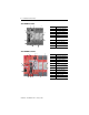
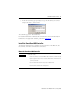
SmartGuard 600 Controllers 1752-L24BBB Controller 2 1 7 3 5 8 9 4 6 10 Number Feature 1 Module status indicators 2 Alphanumeric display 3 Node address switches 4 Baud rate switches 5 USB port 6 DeviceNet communication connector 7 Terminal connectors 8 Input status indicators 9 Output status indicators 10 Service switch Number Feature 1 Module status indicators 7 1752-L24BBBE Controller 1 2 7 3 8 10 5 9 11 6 4 12 7 Publication 1752-IN001C-EN-P - January 2009 2
SmartGuard 600 Controllers 7 Before You Begin Before you install the controller, set its DeviceNet node address and communication rate. IMPORTANT Turn off power to the controller before setting the node address or communication rate via the switches. Do not change the switch settings while the power supply is on. The controller will detect this as a change in the configuration and will switch to the ABORT mode.
SmartGuard 600 Controllers Set the communication rate by using the DIP switch on the front of the controller.
SmartGuard 600 Controllers 9 3. In the the New Entry pop-up dialog box, type the IP address you want to assign to the device, and click OK. The controller appears in the Relation List. For detailed information on EtherNet/IP communication, refer to the EtherNet/IP Performance and Application Solution, publication ENET-AP001. Install the SmartGuard 600 Controller To install the SmartGuard 600 controller, you must mount it on the DIN rail, wire the terminals, and make communication connections.
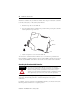
SmartGuard 600 Controllers Mount the controller only to a DIN rail. Follow these steps to mount the controller to an EN 50022-35x7.5 or EN 50022-35x15 DIN rail. 1. Hook the top slot over the DIN rail. 2. Snap the bottom of the controller into position while pressing the controller down against the top of the rail. Top Slot DIN Rail Latch 3. Attach end plates to each end of the DIN rail.
SmartGuard 600 Controllers 11 Ethernet Ground Refer to the Industrial Automation Wiring and Grounding Guidelines, publication 1770-4.1, for additional information. Connecting a Power Supply Power for the controller is provided via an external 24V DC power source. The output hold time must be 20 ms or longer. To comply with the CE Low Voltage Directive (LVD), DeviceNet connections and I/O must be powered by a DC source compliant with safety extra low voltage (SELV) or protected extra low voltage (PELV).
SmartGuard 600 Controllers Power Supply Connections + + + - Wiring the SmartGuard 600 Controller See page 24 for appropriate wire size and torque specifications. Controller Terminal Descriptions Terminal Designation Description V0 Power terminal for internal circuit (logic). G0 Power terminal for internal circuit (logic). V1 Power terminal for input circuits and test outputs. G1 Power terminal for input circuits and test outputs. V2 Power terminal for safety outputs.
SmartGuard 600 Controllers WARNING IMPORTANT 13 If you connect or disconnect the removable terminal block (RTB) while the field-side power is applied, an electrical arc can occur. This could cause an explosion in hazardous location installations. Be sure that power is removed or the area is nonhazardous before proceeding. Prepare stranded wires by attaching ferrules with plastic insulation covers (compliant with the DIN 46228-4 standard).
SmartGuard 600 Controllers Devices, such as light curtains, with current-sourcing PNP semiconductor outputs send a signal to the SmartGuard 600 controller safety-input terminal and do not use a test output. Input Devices with PNP Semiconductor Outputs 4.5 mA Typical V1 24V DC Tx OSSDx INx SmartGuard 600 Controller 24V DC G1 GND Wiring Output Devices ATTENTION Serious injury may occur due to a loss of required safety functions.
SmartGuard 600 Controllers 15 Output Device Wiring V2 SmartGuard 600 Controller 0.5 A Max OUTx 24V DC Load G2 Making Communication Connections WARNING Do not connect or disconnect the communication cable with power applied to this controller or any device on the network, because an electrical arc can occur. This could cause an explosion in hazardous location installations. Be sure that power is removed or the area is nonhazardous before proceeding.
SmartGuard 600 Controllers Connect to the DeviceNet Port Follow these steps to connect to the DeviceNet port. 1. Wire the connector according to the colors on the connector. Wire No. Wire Color Connects to 1 Red V+ 1 2 White CAN H 2 3 — Drain 3 4 Blue CAN L 5 Black V- D D D D D 4 5 2. Attach the connector to the DeviceNet port. 3. Tighten the screws to 0.25…0.3 N•m (2.21…2.65 lb•in).
SmartGuard 600 Controllers 17 Connecting to the Ethernet Port Use an RJ45 connector to connect the controller to the EtherNet/IP network. ATTENTION WARNING The cable length must be less then 100 m (328 ft) between hub and nodes. If you connect or disconnect the Ethernet cable with power applied to this controller or any other device on this network, an electrical arc can occur. This could cause an explosion in hazardous location installations.
SmartGuard 600 Controllers Alphanumeric Status Display The controller’s alphanumeric display provides information about the module’s status. Under normal operating conditions, the display shows the node address of the module, 00…63 in decimal format. If the controller is operating in a standalone configuration (not networked), the display shows ‘nd’. The display flashes when the controller is self-testing, configuring, or in Idle mode.
SmartGuard 600 Controllers 19 3. Contact Rockwell Automation. If your Module Status indicator is flashing red, follow these steps. 1. Configure the switches properly. 2. Reset the configuration data. If your Module Status indicator is solid red (on), follow these steps. 1. Cycle the power supply. 2. Check external wiring. 3. Take corrective actions for noise. 4. Contact Rockwell Automation. If your Module Staus indicator is flashing red and green, follow these steps. 1. Configure the switches properly. 2.
SmartGuard 600 Controllers If your Network Status indicator is off, follow these steps. 1. Cycle the power supply. 2. Check external wiring. 3. Take corrective actions for noise. 4. Contact Rockwell Automation. If your Network Status indicator is on or flashing red, follow these steps. 1. View the Alphanumeric display for the node address of the error and error code. 2. Check that node addresses have not been duplicated. 3. Make sure the communication rate is the same for all nodes. 4.
SmartGuard 600 Controllers 21 USB Communication (COMM U) Status Indicator Descriptions If the USB Communication (COMM U) status indicator is It means Take this action Yellow, flashing The controller is communicating. No action required. Off The controller is not communicating. I/O (inputs 0...15, outputs 0...
SmartGuard 600 Controllers EtherNet/IP Network Status (NS E) Indicator Descriptions If the EtherNet/IP Network Status (NS E) indicator is It means Take this action Off The controller does not have an IP address or is not turned on. Refer to the corrective action following this table. Green, flashing The controller has no established connections but has obtained an IP address. Green, on The controller has at least one established connection (even to the message router).
SmartGuard 600 Controllers 23 EtherNet/IP Communication (COMM E) Status Indicator Descriptions If the EtherNet/IP Communication (COMM E) status indicator is It means Take this action Green, on The controller is communicating on the Ethernet network. No action required. Off The controller is not communicating on the Ethernet network.
SmartGuard 600 Controllers Specifications SmartGuard 600 Controllers - 1752-L24BBB, 1752-L24BBBE Attribute Dimensions (HxWxD), approx. 1752-L24BBB 1752-L24BBBE 99.0(4)x 99.4 x 131.4 mm(5) 99.0(4) x 113.0 x 131.4(5) mm (3.90(4) x 3.91 x 5.18(5) in.) (3.90(4) x 4.48 x 5.18(5) in.) Weight, approx. 460 g (1.23 lb) 575 g (1.54 lb) DeviceNet current load, max 15 mA @ 24V DC Supply voltage 20.4…26.4V DC (24V DC, -15…10%) Inrush current - unit power supply 4.
SmartGuard 600 Controllers 25 SmartGuard 600 Controllers - 1752-L24BBB, 1752-L24BBBE Attribute 1752-L24BBB Test output type Current sourcing Pulse test output current(3) 0.7 A Test output surge current 0.7 A Pulse test off-state voltage, max 1.2V Pulse test output leakage current, max 0.
SmartGuard 600 Controllers Environmental Specifications Attribute 1752-L24BBB Temperature, storage IEC 60068-2-1 (Test Ab, Unpackaged Nonoperating Cold), IEC 60068-2-2 (Test Bb, Unpackaged Nonoperating Dry Heat), IEC 60068-2-14 (Test Na, Unpackaged Nonoperating Thermal Shock): -40…70 °C (-40…158 °F) Temperature, operating IEC 60068-2-1 (Test Ad, Operating Cold), IEC 60068-2-2 (Test Bd, Operating Dry Heat), IEC 60068-2-14 (Test Nb, Operating Thermal Shock): -10…55 °C (14…131 °F) (surrounding air te
SmartGuard 600 Controllers 27 Environmental Specifications Attribute 1752-L24BBB 1752-L24BBBE EFT/B immunity IEC 61000-4-4: • ±2 kV @ 5 kHz on power ports IEC 61000-4-4: • ±2 kV @ 5 kHz on power ports • ±2 kV @ 5 kHz on signal ports • ±1 kV @ 5 kHz on signal ports • ±2 kV @ 5 kHz on communication ports • ±1 kV @ 5 kHz on communication ports Surge transient immunity IEC 61000-4-5: • ±1 kV line-line (DM) and ±2 kV line-earth (CM) on power ports • ±1 kV line-line (DM) and ±2 kV line-earth (CM) on
(1) See the Product Certification link at http://ab.com for Declarations of Conformity, Certificates, and other certifications details. Additional Resources These documents contain additional information concerning related Rockwell Automation products. Resource Description SmartGuard 600 User Manual, publication 1752-UM001 Information on wiring, configuring, operating, and troubleshooting a SmartGuard 600 controller.