
Installation Instruction Manual


SmartGuard 600 Controllers 25
Publication 1752-IN001C-EN-P - January 2009
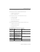
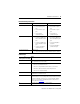
Test output type Current sourcing
Pulse test output current
(3)
0.7 A
Test output surge current 0.7 A
Pulse test off-state voltage, max 1.2V
Pulse test output leakage current,
max
0.1 mA
Muting lamp output current (T3)
• More than 25 mA
• Less than 5 mA
• Normal operation (to avoid fault when used as a muting lamp
output)
• Fault (a fault indication is generated when used as a muting
lamp output)
Output type Current sourcing
Output current 0.5 A
Output surge current 0.5 A
Voltage, off-state output max 1.2V
Leakage current, off-state output,
max
0.1 mA
Heat dissipation 9.3 W under max load
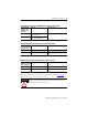
Ethernet Communication
CIP connections Not applicable 2
Auto negotiation Not applicable Supported
Data rate Not applicable 10/100 Mbps
Duplex Not applicable Full/half
Allowable unit
communication bandwidth
Not applicable
3000 pps
(6)
Explicit message
communication
Not applicable
502 Bytes
(7)
(1) V0/G0 for internal logic circuit; V1/G1 for external input devices and test outputs; V2/G2 for external output devices.
(2) Use this Conductor Category information for planning conductor routing. Refer to Industrial Automation Wiring and
Grounding Guidelines, publication 1770-4.1
.
(3) T0...T3 total current at the same time: 1.4 A.
(4) Height includes terminal connectors.
(5) Depth includes DeviceNet connector.
(6) PPS is packets per second. It indicates the number of send or receive packets that can be processed per second.
(7) The maximum message length for class 3 connection and UCMM connection.
SmartGuard 600 Controllers - 1752-L24BBB, 1752-L24BBBE
Attribute 1752-L24BBB 1752-L24BBBE