
User Manual

Rockwell Automation Publication 1752-UM001E-EN-P - June 2014 127
Configure Your Controller for EtherNet/IP Communication Chapter 8
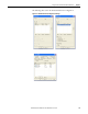
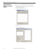
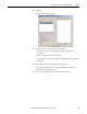
4. Under I/O type, click either Target Input or Target Output.
Target Input means that this data is produced by the SmartGuard
controller and read by the originating device. Target Output means that
this data is produced by the originating device and is sent to the
SmartGuard controller.
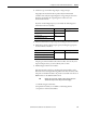
If you have checked Target Input, you can include the following status
information in the I/O assembly.
5. Add status information for input types by checking the Status checkboxes.
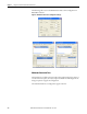
6. Add local I/O monitor data for input types by checking the appropriate
Local I/O Monitor checkbox.
Output types cannot include local I/O monitor data. You can only read
input and output values; you cannot directly write to them.
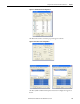
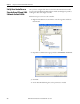
7. Add Routing I/O data for the modules.
If the SmartGuard controller is controlling safety DIO modules on the
DeviceNet network, using the Routing I/O feature allows the values of the
I/O points on the DIO modules to be passed to a standard controller or an
HMI interface on the EtherNet/IP network.
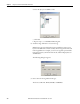
a. Under Routing I/O, click New.
b. Expand the node that you would like to add routing data for.
c. Expand one of the listed assemblies.
Tag Name Data Size Attribute Type
General Status Byte Non-safety
Local Input Status Word
Local Output Status Byte
Test Output/Muting Lamp Status
Tag Name Data Size Attribute Type
Local Input Monitor 1 (inputs 0...7) Byte Non-safety
Local Input Monitor 2 (inputs 8...15)
Local Output Monitor (outputs 0...7)
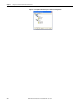
TIP
Modules appear only in the routing I/O table after they have been
added to the Safety Scan list and you have clicked Apply.