
User Manual

202 Rockwell Automation Publication 1752-UM001E-EN-P - June 2014
Appendix B Status Indicators
Identifying EtherNet/IP
Errors Using Status Indicators
and Alphanumeric Display
Use these tables to interpret the color and status combinations of the status and
alphanumeric display indicators and take corrective action where applicable.
For the 1752-L24BBBE controller, when the IP address display switch for 1
second or longer, the display shows the EtherNet/IP address that is set. The error
code ‘n4’ is displayed if an error occurs in EtherNet/IP configuration.
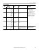
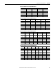
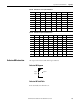
Table 33 - EtherNet/IP Controller Errors
Indicators
Error Log Cause Corrective Action
MS NS Alphanumeric Display
(1)
Code
Off Red, on UF System Failure An EtherNet/IP adaptor hardware fault
occurred.
Cycle the power supply. If a failure occurs
again, replace the controller.
Red, on --- F0 An IP address duplication fault occurred. Check the IP address of the other devices, and
set an address that does not duplicate any
other.
Off --- E3 A BOOTP server connection fault occurred. 1. Make sure the cable is connected correctly.
2. Make sure the BOOTP server is operating
normally.
Off --- F2 A Basic setting logic processing fault occurred. Check the configuration. If a failure occurs
again, replace the controller.
Off Red,
flashing
E9 An EtherNet/IP memory fault occurred. Cycle the power supply. If a failure occurs
again, replace the controller.
Off Red,
flashing
F4 An EtherNet/IP communication controller
fault occurred.
Red,
flashing
--- L9 An EtherNet/IP standard target
communication error occurred.
1. Make sure the same communication
settings are used for each node
2. Make sure the cables are not disconnected
or bent.
3. Make sure power is supplied to the
originator.
Off --- E1 A Link OFF error occurred. 1. Make sure the same communication
settings are used for each node
2. Make sure the cables are not disconnected
or bent.
3. Make sure power is supplied to the hub.
(1) Display alternates between error code and n4.