
User Manual

212 Rockwell Automation Publication 1752-UM001E-EN-P - June 2014
Appendix C Logic Functions Command Reference
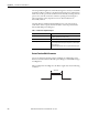
Reset Set FIip-flop Error Handling
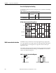
Use this table to diagnose and reset a discrepancy error condition in the RS Flip-
flop instruction.
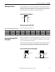
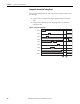
RS Flip-flop Instruction Timing Chart
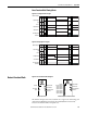
Multi-connector Instruction
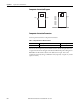
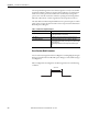
The Multi-connector instruction converts input signals for up to eight inputs
into output signals for up to eight outputs. The input signals and output signals
are associated one-to-one for signals one to eight. The status of other input
signals has no effect.
The number of inputs and outputs can be increased to eight on the I/O Settings
tab of the Function Block Properties dialog box in RSNetWorx for DeviceNet
software. The default setting is one.
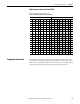
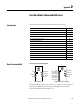
Multi-connector Instruction Diagram
Table 4 - Error Detection and Reset for RS Flip-flop Instruction
Error Condition Status When an Error Occurs To Reset the Error Condition
Output Enable Fault
Present
Input and Reset are active
simultaneously
OFF
(Safety State)
ON Make one of the signals inactive.
Input
Fault Present
Output Enable
Reset
Input 1
Input 2
Output 1Input 1
Input 4
Input 3
Input 5
Input 6
Input 7
Input 8
Output 1
Output 2
Output 3
Output 4
Output 5
Output 6
Output 7
Output 8
Default Connections
Maximum I/O for Multi-connector Instruction