
User Manual


Rockwell Automation Publication 1752-UM001E-EN-P - June 2014 253
Function Blocks Command Reference Appendix D
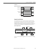
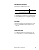
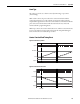
Timing Chart
The muting mode in the following charts is parallel muting with 2 sensors.
Figure 75 - Normal Operation of the Override Function
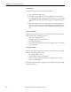
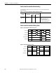
Figure 76 - Override Signal Goes Off During Override
AOPD Input 1 (NC)
AOPD Input 2 (NC)
Muting Signal 11
Muting Signal 12
Output Enable
Override Status
Override Time
Override Discrepancy
Time
Override Input 2 (NO)
Override Input 1 (NO)
Fault Present
Muting Status
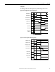
AOPD Input 1 (NC)
AOPD Input 2 (NC)
Muting Signal 11
Muting Signal 12
Output Enable
Override Status
Override Time
Override Input 1 (NO)
Fault Present
Muting Status