
User Manual

Rockwell Automation Publication 1752-UM001E-EN-P - June 2014 271
Appendix F
Application and Configuration Examples
Introduction
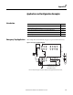
Emergency Stop Application
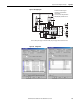
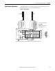
This example shows a dual channel emergency stop switch with manual reset.
Figure 91 - Emergency Stop Wiring Diagram
Topic Page
Emergency Stop Application 271
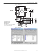
Safety Gate Application with Automatic Reset 273
Dual Zone Safety Gate Application Using Emergency Stop Switch with Manual Reset 274
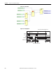
Safety Mat Application 276
Light Curtain Application 279
V1
G1 T 0
T1
I1
I0
I3
I5
I2
I4
I6
I7
T2
T3
E1
S1
11 21
12 22
O1
O0
V2 G 2
O3 O5
O2 O4 O6
O7
E2
KM 1 KM 2
I9
I8
I1 1
I1 3
I1 0
I1 2
I1 4
I1 5
KM 1 - N C
KM 2 - N C
M
KM1
KM2
S2
E1 and E2: 24V dc Power Supplies
S1: Emergency Stop Switch
S2: Reset Switch (N.O. Contact)
KM1 and KM2: Contactors
Connect a 24V dc power supply to terminals V0 and G0, the power supply terminals for internal circuits.