
User Manual

Rockwell Automation Publication 1752-UM001E-EN-P - June 2014 279
Application and Configuration Examples Appendix F
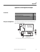
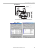
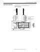
Light Curtain Application
This example shows a dual channel safety light curtain with manual reset and
dual channel emergency stop switch with manual reset.
Figure 107 - Wiring Diagram
1
0
3
5
2
4
6
7
9
8
1
3
0
2
4
5
V1
G1 T0
T1
T2
T3
O1
O0
V2 G2
O3 O5
O2 O4 O6
O7
M
KM1
KM2
E1
E2
KM1-NC
KM2-NC
KM1 KM2
S2
S1
S3
Connect a 24V dc power supply to terminals V0 and G0, the power supply terminals for internal circuits.
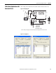
E1 and E2: 24V dc Power Supplies
S1: Reset Switch
S2: Reset Switch
S3: Emergency Stop Push Button
KM1 and KM2: Contactors
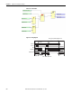
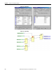
Aux Output (White)
Safety Output 1 (Gray)
Safety Output 2 (Pink)
0V (Blue)
+24V (Brown)
Reset Input (Yellow)
Test Input (Black)
0V (Blue)
440 L
Receiver
440 L
Transmitte r