
User Manual


34 Rockwell Automation Publication 1752-UM001E-EN-P - June 2014
Chapter 2 Installing and Wiring the SmartGuard 600 Controller
standard Ethernet cable. When connecting the SmartGuard controller directly to
your personal computer or a NIC card, use a cross-over (null modem) cable.
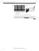
Wiring the SmartGuard 600
Controller
Use cables of 30 m (98 ft) or less.
ATTENTION: The cable length must be less then 100 m (328 ft) between hub
and nodes.
WARNING: If you connect or disconnect the Ethernet cable with power applied
to this controller or any other device on this network, an electrical arc can occur.
This could cause an explosion in hazardous location installations. Be sure that
power is removed or the area is nonhazardous before proceeding.
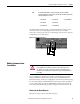
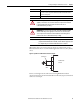
Pin No. Pin Name Pin placement
8 Not used
7 Not used
6RD-
5 Not used
4 Not used
3RD+
2TD-
1TD+
8
1
Attribute Value
Wire type Copper
Wiring category
(1)
(1) Use this Conductor Category information for planning conductor routing. Refer to Industrial Automation Wiring and Grounding
Guidelines, publication 1770-4.1
.
2 - on power, signal, and communication ports
Wire size For power supply and I/O, use 0.2…2.5 mm
2
(12…24 AWG) solid wire, or
0.34…1.5 mm
2
(16…22 AWG) stranded flexible wire. Before connecting,
prepare stranded wires by attaching ferrules with plastic insulation collars
(DIN 46228-4 standard compatible).
I/O Terminal Screw Torque 0.56…0.79 N•m (5…7 lb•in)
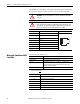
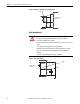
Terminal Designation Description
V0 Power terminal for internal circuit (logic).
G0 Power terminal for internal circuit (logic).
V1 Power terminal for input circuits and test outputs.
G1 Power terminal for input circuits and test outputs.
V2 Power terminal for safety outputs.
G2 Power terminal for safety outputs.