Installation Instructions Logix5553 Controller Before You Begin Use this document as a guide for installing and powering-up your Logix5553™ controller. You should already be familiar with the ControlLogix™ system components. See the documentation references for detailed information.
Logix5553 Controller Important User Information Because of the variety of uses for the products described in this publication, those responsible for the application and use of this control equipment must satisfy themselves that all necessary steps have been taken to assure that each application and use meets all performance and safety requirements, including any applicable laws, regulations, codes and standards.
Logix5553 Controller 3 European Communities (EC) Directive Compliance If this product has the CE mark it is approved for installation within the European Union and EEA regions. It has been designed and tested to meet the following directives.
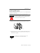
Logix5553 Controller Handling the ControlLogix system components Take these precautions to guard against ESD damage: ATTENTION ! Electrostatic discharge can damage the components.
Logix5553 Controller 5 What you need to do Before you can install a Logix5553 controller, you must perform these actions: ✓ Install a ControlLogix chassis according to the ControlLogix Chassis Installation Instructions, publication 1756-5.80 ✓ Install a ControlLogix power supply according to the corresponding installation instructions: Install this power supply: According to this publication: 1756-PA72 ControlLogix Power Supplies Installation Instructions, publication 1756-5.
Logix5553 Controller Verify that you have all the components These components ship with the Logix5553 controller: Component: 1756-BA1 battery key catalog number label In addition, you may need: Component: Description: serial cable 1756-CP3 You can also use the 1747-CP3 cable from the SLC product family.
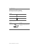
Logix5553 Controller 7 Install the battery ATTENTION Only install a 1756-BA1 battery. If you install a different battery, you may damage the controller. ! WARNING For safety information on the handling of lithium batteries, including the handling and disposal of leaking batteries, see Guidelines for Handling Lithium Batteries, publication AG-5.4. ! 1. Install a 1756-BA1 battery.
Logix5553 Controller 2. Attach the battery label: a. Write on the battery label the date you install the battery. b. Attach the label to the inside of the controller door.
Logix5553 Controller 9 Install the Logix5553 controller You can place the Logix5553 controller in any slot. You can use multiple Logix5553 controllers in the same chassis. The Logix5553 controller comes with a memory board already installed. ATTENTION ! Do not take the Logix5553 controller apart or try to remove the memory board from the controller. These components must not be modified. Removing or modifying the memory board irreparably damages the controller. 1.
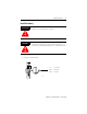
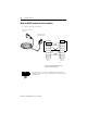
Logix5553 Controller Make an RS-232 connection to the controller 1. Obtain a 1756-CP3 serial cable. 9-pin, male D-shell straight cable end 9-pin, female D-shell right-angle cable end 40043 1 CD 1 CD 2 RDX 2 RDX 3 TXD 3 TXD 4 DTR 4 DTR COMMON COMMON 6 DSR 6 DSR 7 RTS 7 RTS 8 CTS 8 CTS 9 9 straight cable end right-angle cable end 40046 This cable must be shielded and tied to the connector housing at both ends.
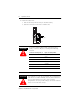
Logix5553 Controller 11 2. Connect the cable to the controller. WARNING When you connect or disconnect the serial cable while backplane power is on, an electrical arc can occur. In hazardous locations, this could cause an explosion.
Logix5553 Controller Select the operating mode of the controller 1.
Logix5553 Controller 13 Interpret the controller LEDs Indicator: RUN I/O 40002 RS232 BAT OK Color: Description: off The controller is in Program or Test mode. green The controller is in Run mode. off Either: • There are no devices in the I/O configuration of the controller. • The controller does not contain a project (controller memory is empty). green The controller is communicating with all the devices in its I/O configuration.
Logix5553 Controller Specifications Description: Specification: user memory 1.5 Mbytes backplane current +5V dc +24V dc 1.20A 0.02A thermal dissipation 4.25W power dissipation 3.0W operating temperature 0° to 60° C (32 to 140° F) storage temperature -40° to 85° C (-40 to 185° F) relative humidity 5% to 95% noncondensing vibration 10 to 500 Hz 2.0 G maximum peak acceleration operating shock 30G peak for 11ms storage shock 50G peak for 11ms weight 12.7 oz.
Logix5553 Controller 15 CSA Hazardous Location Approval CSA certifies products for general use as well as for use in hazardous locations. Actual CSA certification is indicated by the product label as shown below, and not by statements in any user documentation.
Logix5553 Controller Approbation d’utilisation dans des environnements dangereux par la CSA La CSA certifie des produits pour une utilisation générale aussi bien que pour une utilisation en environnements dangereux. La certification CSA en vigueur est indiquée par l'étiquette produit et non par des indications dans la documentation utilisateur.
Logix5553 Controller 17 Other Publications This product has the following additional manuals: • ControlLogix System User Manual, publication 1756-UM001 • Logix5000 Controllers Common Procedures Programming Manual, publication 1756-PM001 • Logix5000 Controllers General Instruction Set Reference Manual, publication 1756-RM003 • Logix5000 Controllers Process Control and Drives Instruction Set Reference Manual, publication 1756-RM006 • Logix5000 Controllers Motion Instruction Set Reference Manual, publication
Publication 1756-IN017A-EN-P - August 2000 PN 957308-43 © 2000 Rockwell International Corporation. Printed in the U.S.A.