
User Manual Owner's manual


Rockwell Automation Publication 1756-UM535D-EN-P - November 2012 17
About Enhanced Redundancy Systems Chapter 1
Features Not Supported
• Any motion feature
• Any SIL3 functional safety feature within the redundancy controllers
• Firmware Supervisor
• Event Tasks
• Firmware revision 19.052 for 1756-L7x controller
Enhanced Redundancy
System Components
Communication between a redundant chassis pair that includes matching
components makes redundancy possible.
Each chassis in the redundant chassis pair contains these
ControlLogix components:
• One ControlLogix power supply - Required
• One ControlLogix redundancy module - Required
Redundancy modules link the redundant chassis pair to monitor events in
each of chassis and initiate system responses as required.
• At least one ControlLogix ControlNet or EtherNet/IP communication
module - Required
• Up to two controllers - Optional
In addition, redundant chassis are connected to other components outside the
redundant chassis pair, for example, remote I/O chassis or human-machine-
interfaces (HMIs).
For more information about components you can use in an enhanced
redundancy system, see Chapter 2
, Design an Enhanced Redundancy System on
page 23.
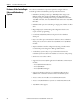
IMPORTANT
For Ethernet modules, signed and unsigned firmware are available. Signed modules provide the
assurance that only validated firmware can be upgraded into a module.
Signed and unsigned firmware:
• Both signed and unsigned firmware are available.
• Product is shipped with unsigned firmware. To obtain signed firmware, you must upgrade your
product’s firmware.
• To obtain signed and unsigned firmware, go to Get Support Now
.
• Once signed firmware is installed, subsequent firmware upgrades must be signed also.
There are no functional/feature differences between signed and unsigned communication modules.