RSFieldbus and the 1757-FFLD Linking Device 1757-FFLD Programming Manual
Important User Information Solid state equipment has operational characteristics differing from those of electromechanical equipment. Safety Guidelines for the Application, Installation and Maintenance of Solid State Controls (Publication SGI-1.1 available from your local Rockwell Automation sales office or online at http://www.rockwellautomation.com/literature) describes some important differences between solid state equipment and hard-wired electromechanical devices.
Preface This programmig manual describes how to use the 1757-FFLD linking device along with RSFieldbus in applications with the FOUNDATION Fieldbus network. This document provides technical, network setup and configuration information with guidelines on application function block use. In addition, this manual offers references to third party device configuration guidelines for the Foundation Fieldbus and the linking device.
Preface 4 Related Documentation For information on the Rockwell Software products found in this manual, refer to the following publications: • RSFieldbus Installation Guide, publication RSFBUS-IN001 • RSFieldbus User Manual, publication RSFBUS-UM001 • RSView Supervisory Edition User’s Guide, publication VIEWSE-UM003C These FOUNDATION Fieldbus Specification documents contain information that you may find helpful as you read this manual: • System Architecture, publication FF-800 • Technical Overview, publi
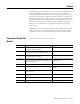
Chapter 1 System Requirements In This Chapter Purpose of this Chapter For See Page Purpose of this Chapter 1-1 Foundation Fieldbus Description 1-2 Hardware Requirements 1-4 Software Requirements 1-12 Additional Resources 1-12 This chapter describes the components of a typical fieldbus system, including the Rockwell Automation Linking Device, 1757-FFLD. Refer to the Glossary for further explanation of fieldbus terms and concepts.
1-2 System Requirements Hardware Requirements To build a simple fieldbus system, you need: • Power supply • Power conditioner • Fieldbus cable • Field devices • Connector blocks • Terminal blocks • Terminators • 1757- FFLD linking device • Personal computer Power Supply The following power supplies are available according to the referenced Fieldbus Foundation Physical Layer Profile Specification: Type 131 Non-I.S. Power supply intended for feeding and I.S. barrier.
System Requirements 1-3 resistive/inductive network that is either external or built into the fieldbus power supply. Fieldbus Cable The preferred fieldbus cable is specified in the IEC/ISA Physical Layer Standard, Clause 22.7.2 for conformance testing. It is referred to as type “A” fieldbus cable. This cable will probably be used in new installations. Other types of cable can also be used. The alternate preferred fieldbus cable is a multiple, twisted pair cable with an overall shield.
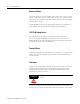
1-4 System Requirements Connector Blocks Connector blocks are optional coupling devices. They can be used to connect wire to a fieldbus device, or to another section of wire (e.g. at a junction block). Connector blocks are useful for installations where devices may be periodically disconnected or moved. Standard fieldbus connectors are specified in Annex B of the ISA Physical Layer Standard and Annex A of the IEC Physical Layer Standard.
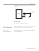
System Requirements 1-5 the trunk. The following illustration shows a sSimple Fieldbus network with terminators FFI Trunk Wire Pair FFLD Fieldbus Digital Field Device T Signals Terminator T Terminator Personal Computer You need a computer to run RSFieldbus software. Software Requirements RSFieldbus and RSLogix 5000 software for are required. As an option, you can use RSView Supervisory Edition software for specific applications.
1-6 System Requirements Web Sites • Rockwell Automation – External: http://domino.automation.rockwell.com/applications/gs/region/gt swebst.nsf/pages/Process_Solutions_Home – Internal: http://rain.ra.rockwell.com (select Process Solutions from the A-Z menu) • FOUNDATION Fieldbus: http://www.fieldbus.org/ • Tech Support: – For Knowledge-base information, go to the Tech support Web site: http://support.rockwellautomation.
Chapter 2 Set Up A System In This Chapter Purpose of this Chapter For See Page Purpose of this Chapter 2-1 Hardware Requirements 2-2 Software Requirements 2-5 Set Up A System 2-6 Physical Media 2-7 Network Basics 2-20 Things to Consider When Setting Up a System 2-27 Additional Resources 2-27 This chapter describes the components of a typical fieldbus system and how to set up and prepare your system for operation.
2-2 Set Up A System Hardware Requirements To build a simple fieldbus system, you need: • Power supply • Power conditioner • Fieldbus cable • Field devices • Connector blocks • Terminal blocks • Terminators • 1757- FFLD linking device • Personal computer Power Supply The following power supplies are available according to the referenced Fieldbus Foundation Physical Layer Profile Specification: Type 131 Non-I.S. Power supply intended for feeding and I.S. barrier. Output voltage depends on barrier rating.
Set Up A System 2-3 resistive/inductive network that is either external or built into the fieldbus power supply. Fieldbus Cable The preferred fieldbus cable is specified in the IEC/ISA Physical Layer Standard, Clause 22.7.2 for conformance testing. It is referred to as type “A” fieldbus cable. This cable will probably be used in new installations. Other types of cable can also be used. The alternate preferred fieldbus cable is a multiple, twisted pair cable with an overall shield.
2-4 Set Up A System Connector Blocks Connector blocks are optional coupling devices. They can be used to connect wire to a fieldbus device, or to another section of wire (e.g. at a junction block). Connector blocks are useful for installations where devices may be periodically disconnected or moved. Standard fieldbus connectors are specified in Annex B of the ISA Physical Layer Standard and Annex A of the IEC Physical Layer Standard.
Set Up A System 2-5 the trunk. The following illustration shows a sSimple Fieldbus network with terminators FFI Trunk Wire Pair FFLD Fieldbus Digital Field Device T Signals Terminator T Terminator Personal Computer You need a computer to run RSFieldbus software. Software Requirements RSFieldbus and RSLogix 5000 software for are required. As an option, you can use RSView Supervisory Edition software for specific applications.
2-6 Set Up A System Set Up A System When setting up a fieldbus system, you must first install and configure your software and all fieldbus devices. The following figure is a simplified diagram of a fieldbus system using RSFieldbus. Figure 2.
Set Up A System Physical Media 2-7 Power Considerations Fieldbus devices may be either powered from the segment (bus) or locally powered, depending on the design. If at all possible, field devices should be bus powered. Power Supplies Power supplies shall comply with IEC 61158-2 criteria and performance requirements, with preferential consideration given to the low-power signal option.
2-8 Set Up A System Additionally, power conditioners may have an internal terminator which should be considered when placing terminators on the network. Signal Wire Polarity The combination signal/power wires have a plus (+) and minus (-) polarity associated to the power conditioner outputs, which must be wired to the appropriate terminals on the devices. Some devices are polarity insensitive, meaning they still work if you connect the positive wire to the negative terminal, and vice-versa.
Set Up A System 2-9 • Additional current consumption due to one spur short-circuit fault (10ma) The length of a fieldbus wiring system and the number of devices on a network/segment are limited by the power distribution, attenuation, and signal distortion. Refer to ISA 50.02 for the limitations on cable length. Fieldbus Network Topologies A network topology refers to the shape and design of a fieldbus network.
2-10 Set Up A System Figure 2.3 Rockwell linking device with a Simple Two-Port Fieldbus Network Terminator Terminator Wire Pair T T Fieldbus Device TwoPort Linking Device Terminator Terminator Wire Pair T T Fieldbus Device T Power Conditioner Power Conditioner Power Supply Tree Topology - Chicken Foot This topology consists of a single fieldbus segment connected to a common junction box to form a network.
Set Up A System 2-11 Figure 2.4 Tree Topology (Chicken Foot) Junction Box 1 Linking ice T Trunk T Note: The ìTî is for Terminator.
2-12 Set Up A System Figure 2.5 and Figure 2.6 are examples of chicken foot topologies using Relcom Blocks. Figure 2.5 Tree Topology (Chicken Foot) Using Relcom Blocks Isolated Terminator Expansion Block Block To H1 Linking Device Trunk T T Power Conditioner D/1 D/2 D/3 D/4 D/5 D/6 D/7 Figure 2.
Set Up A System 2-13 Spur Wire Length Calculations Spur lengths can vary from 1 meter to 200 meters. If you have a choice about spur length, the general rule is that the shorter the spur, the better. A spur less than 1 meter is considered a splice. Table 2.1 below lists recommended spur lengths for devices. Table 2.
2-14 Set Up A System Figure 2.8 Proper Shielding for a Tree Network F F F FFLD T T All Shields Tied Here Signal Quality When a fieldbus network’s signal quality is poor, it can cause intermittent loss of communication to devices, unreasonably long downloads, and lost data. The following components are critical to achieving good signal quality: • Shielded two wire cable, preferably specifically designed for fieldbus. The type of cable will determine overall length of the trunks and drops.
Set Up A System 2-15 Protocol Analysis There are a number of ways in which you can verify that the network you have set up will perform properly. A protocol analyzer is a tool that allows you to test for the content of the message sent, what the messages mean, and what sequence the fieldbus devices talk to each other. It should be noted, however, that a protocol analyzer is an advanced tool with a complex range of functions.
2-16 Set Up A System Fieldbus Network Testers Other testers are used to monitor and characterize network signals. The Relcom Fieldbus Network Monitor (FBT-3) can be used to examine the operation of a live fieldbus network, without interfering with its operation.(1) The FBT-3 will verify the DC voltage on the network and check how noisy the network is.
Set Up A System 2-17 Another way of testing the signal quality of a network is to use an oscilloscope. We recommend a hand-held battery-operated unit because of its small size and ease of use. The Fluke 199-3 ScopeMeter is one such scope. Figure 2.9 Fluke 199-3 200MHz ScopeMeter Other scopes that can be used include the TPI-E1505, the Extech-381275 (www.professionalequipment.com), and the Techtronix THS700 Series (www.tek.com).
2-18 Set Up A System Figure 2.10 An Ideal Fieldbus Communications Signal 75-500 mv Max Noise 75 mv (pk-pk) 75-500 mv Good Network Scope Display In order to analyze a fieldbus network signal, you must know what constitutes a good signal versus a bad one. Figure 2.11 represents a normal signal consisting of two terminators. Figure 2.11 Good Network Signal (1) (1) Publication 1757-PM002A-EN-E - June 2006 FF Engineering Guide (11.4.
Set Up A System 2-19 Bad Network Scope Display Bad network signals can inhibit the performance of your network. A common reason for bad signals is the addition of one or more unnecessary terminators in a network. Remember, there can be only two terminators per bus segment. WAR Figure 2.12 shows a bad signal due to only one terminator in a system, while Figure 2.13 shows a bad signal due to one extra terminator (3 total). Figure 2.12 Bad Network Signal Due to One Terminator(1) (1)11.4.
2-20 Set Up A System Figure 2.13 Bad Network Signal Due to Three Terminators(1) Network Basics When using the linking device, there are two networks that must be considered: the HSE network and the H1 network. HSE HSE stands for High Speed Ethernet. HSE is the Fieldbus Foundation's backbone network running Ethernet and IP. An HSE field device is a fieldbus device connected directly to a High Speed Ethernet (HSE) fieldbus.
Set Up A System 2-21 binary number is important because it will determine which class of network the IP address belongs to. An IP address consists of two parts, one identifying the network and one identifying the node, or host. The class of the address determines which part belongs to the network address and which part belongs to the node address. All nodes on a given network share the same network prefix, but must have a unique host number.
2-22 Set Up A System Default Configuration The default configuration of the linking device is to use DHCP and a BootP server. The Dynamic Host Configuration Protocol (DHCP) is an Internet protocol for automating the configuration of computers that use TCP/IP. DHCP can be used to automatically assign IP addresses, to deliver TCP/IP stack configuration parameters such as the subnet mask and default router, and to provide other configuration information.
Set Up A System 2-23 2. In the RSLinx window, select Communications from the drop-down list and Configure Drivers from the menu. 3. Select Ethernet IP Driver from the drop-down menu 4. Click Add New. 5. Click OK (to use the default driver name).
2-24 Set Up A System 6. Click OK to use the default configuration settings as shown. The AB-ETHIP-1 Driver should show “Running.”. 7. Close the configuration window. 8. Select Communications from the drop-down list and RSWho from the menu. 9. Expand the AB-EtherIP-1 driver to see the devices on the network. In this case, there are two linking devices.
Set Up A System 2-25 However, it is still best to call RA Tech Support (see page 1-6) if this situation occurs, and for other problems concerning DHCP. H1 H1 Fieldbus is a digital, serial, multidrop data bus for communication with industrial devices or systems. The Physical Layer provides for transparent transmission of data between Data Link Layer entities across physical connections.
2-26 Set Up A System required to configure the H1 network, and the ability for the network to perform necessary housekeeping. IMPORTANT Intrinsic safety barriers cause the maximum device number per H1 to change to 4 to 6 devices, depending on the power consumption of the devices installed and the manufacturers’ specifications for both the barrier and the transmitter. Scheduling Scheduling is done automatically.
Set Up A System 2-27 • 248-251 are available for devices with no permanent address such as new devices or decommissioned devices. • 252-255 are available for temporary devices, such as handhelds. Naming Conventions for Devices Each FOUNDATION fieldbus device must have a unique physical device tag. The device tag shall be used for the device diagnostic alarm faceplate.
2-28 Set Up A System Web Sites • Rockwell Automation – External: http://domino.automation.rockwell.com/applications/gs/region/gt swebst.nsf/pages/Process_Solutions_Home – Internal: http://rain.ra.rockwell.com (select Process Solutions from the A-Z menu) • FOUNDATION Fieldbus: http://www.fieldbus.org/ • Tech Support: – For Knowledge-base information, go to the Tech support Web site: http://support.rockwellautomation.
Chapter 3 Basic Function Blocks In This Chapter For See Page Purpose of this Chapter 3-1 Basic Function Blocks 3-1 Put Blocks in Auto 3-2 Block Errors 3-4 Naming Conventions 3-4 Differences Between Configuration and Calibration 3-5 Initial Configuration: Virtual Communication Relationships 3-6 Purpose of this Chapter This chapter deals with the basic usage of function blocks within transmitters and the minimum configuration needed to make these transmitters active.
3-2 Basic Function Blocks Transducer Block The Transducer Block acts as the connection between the physical world of wires and circuit boards to the electronic world of RSFieldbus. The XDCR allows the I/O blocks to access data on the wire and bring it into RSFieldbus to be used for control loops. The important parameters within the XDCR are MODE_BLK and TERMINAL_NUMBER. Putting the MODE_BLK to AUTO allows the function block to be active upon download.
Basic Function Blocks 3-3 To look at how to clear IMAN from individual blocks, refer to the Function Block Manual, page 1-14.
3-4 Basic Function Blocks Block Errors The BLOCK_ERR parameter gives a non-specific reason for the block being in error. The most common errors have to do with a block being Out Of Service. There are various other block-specific reasons for certain blocks to be in error, including ranges being required and logical parameters needing to be set. To find a specific error given by the BLOCK_ERR parameter, reference the function block in the Function Block Manual, or your specific vendor’s manual.
Basic Function Blocks Differences Between Configuration and Calibration 3-5 Definition of Calibration Calibration is the process of adjusting certain device parameters in order that the physical quantities measured meet an established standard for accuracy. Calibration Parameters in the Transducer Block Transducer Blocks are used to configure devices. Transducer Blocks decouple Function Blocks from the local input/output functions required to read sensors and command output hardware.
3-6 Basic Function Blocks Relationship of Output Function Blocks to the Transducer put rameters Block Algorithm Output Snap of Transducer Block Inputs Channel Output Transducer Block I/O Subsystem Manufacturer Specific Initial Configuration: Virtual Communication Relationships Virtual Communication Relationships (VCRs) are communication links on an H1 network. A total of 128 VCR’s are possible within the linking device, and these VCRs are restricted to 32 per H1 channel.
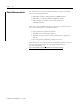
Basic Function Blocks 3-7 • QUB: Queued User-triggered Bidirectional Table 3.1 : VCR Classes BNU QUU QUB Permitted Roles Publisher, Subscriber Source, Sink Client, Server, Peer Conveyance Paths 1 1 2 Conveyance Policy Buffered Queued Queued Transmission Policy Network Scheduled User Triggered User Triggered The quantity of each class of VCR that is available for configuration and communication is device dependent.
3-8 Basic Function Blocks MaximumNumberOfServerVcrs =5 MaximumNumberOfSourceVcrs =8 MaximumNumberOfSinkVcrs =0 MaximumNumberOfPublisherVcrs = 64 MaximumNumberOfSubscriberVcr s = 64 The user would be under the impression that there are 64 publishers and 64 subscribers available. This is both correct and incorrect at the same time. The user can correctly use the total quantity, but it must be evenly distributed among the four H1 channels that the linking device uses.
Basic Function Blocks 3-9 VCRs: 2 total; 1 Publisher, 1 Subscriber LGX FB 1 2. Linking Device: 1 Subscriber Device 1: 1 Publisher VCRs: 2 total; 1 Publisher, 1 Subscriber LGX FB 1 3. Linking Device: 2 Subscribers Device 1: 2 Publishers VCRs: 4 total; 2 Publishers, 2 Subscribers FB 1 LGX FB 2 4.
3-10 Basic Function Blocks Device 2: 1 Publisher VCRs: 2 total; 2 Publisher, 2 Subscriber Device 1 FB 1 Device 2 LGX FB 2 5. Linking Device: 1 Subscriber Device 1: 1 Publisher (Internal Links use link objects rather than VCRs) VCRs: 2 total; 1 Publisher, 1 Subscriber Device 1 FB 1 LGX FB 2 6.
Basic Function Blocks 3-11 VCRs: 2 total; 1 Publisher, 1 Subscriber Device 1 FB 1 LGX FB 2 7. Linking Device: 2 Publishers (assuming two links are different LGX outputs) Device 1: 2 Subscribers VCRs: 2 total; 1 Publisher, 1 Subscriber Device 1 FB 1 LGX Device 2 FB 2 8.
3-12 Basic Function Blocks VCRs: 2 total; 1 Publisher, 1 Subscriber Device 1 FB 1 LGX FB 2 9. Linking Device: 1 Publisher & 1 Subscriber Device 1: 1 Publisher & 1 Subscriber VCRs: 4 total; 2 Publisher, 2 Subscriber FB 1 LGX 10.
Basic Function Blocks 3-13 11. Linking Device: 2 Publishers & 1 Subscriber Device 1: 1 Publisher & 2 Subscribers VCRs: 6 total; 3 Publisher, 3 Subscriber Device 1 FB 1 LGX FB 2 12. Linking Device: 2 Publishers & 2 Subscribers Device 1: 2 Publishers & 2 Subscribers VCRs: 8 total; 4 Publisher, 4 Subscriber FB 1 LGX FB 2 13.
3-14 Basic Function Blocks VCRs: 8 total; 4 Publisher, 4 Subscriber Device 1 FB 1 LGX Device 2 FB 2 14. Linking Device: 2 Publishers & 2 Subscribers Device 1: 1 Publisher Device 2: 1 Publisher Device 3: 1 Subscriber Device 4: 1 Subscriber VCRs: 8 total; 4 Publisher, 4 Subscriber Device 1 Device 3 FB 1 FB 3 Device 2 LGX FB 2 15.
Basic Function Blocks 3-15 VCRs: 6 total; 3 Publisher, 3 Subscriber Device 1 FB 1 LGX QUU and QUB VCR Classes The QUU and QUB VCR classes are defined as user triggered. During the unscheduled portion of Foundation Fieldbus communications, these are the class of communication that occur when the available time is sensed by the devices. QUU and QUB communications take place when the Link Active Scheduler passes the token to the devices, allowing them to communicate.
3-16 Basic Function Blocks Publication 1757-PM002A-EN-E - June 2006
Chapter 4 Applications In This Chapter RSFieldbus PID With ControlLogix Application Example 1 For See Page RSFieldbus PID With ControlLogix Application Example 4-1 Device Replacement 4-40 PID Guide 4-43 This example shows you how to incorporate the following devices into a project with a ControlLogix controller: • Rockwell Automation 1757-FFLD linking device • Smar FI 302 • Smar LD 292 Publication 1757-PM002A-EN-E - June 2006
4-2 Applications This strategy will use the Fieldbus devices as I/O and the ControlLogix controller as the PID controller. ControlLogix SP P-10 PIC 1-10 OP PV Steam V-3 Steam Drum PT 1-11 P-9 P-8 E-2 OUT= 904.98608 LD292 AI OUT_0 = 23 FI302 AO FFLD LGX IN_0 = 904.98608 IN_1 = 23 CAS_IN = 23 BKCAL_OUT = 23 Create A New RSFieldbus Project Open a Project 1. Select Start ⇒ Programs ⇒ Rockwell Software ⇒ RSFieldbus ⇒ RSFieldbus.
Applications 4-3 2. Click OK. The RSFieldbus window opens. 3. Click , and select Project. 4. Enter >PID < for the name and click Save. Save your project often to prevent loss of time and work. The Project window opens. Define the Server This step defines the OPC Server and where it is located. 1. In the Project window, right-click the Fieldbus Networks icon and select Communication Settings. The Communication Settings window opens. 2.
4-4 Applications Tags cannot include a “.” (period). If a separator is needed, we suggest using an “_” (underscore). The HSE is added to the Project. Define the HSE Host This step defines your PC as the HSE Host. 1. In the Project window, right-click the HSE and select Expand. The HSE window opens. 2. In the HSE window, right-click the HSE and select New Bridge. The New Bridge window opens. 3. Select the following settings: give the New Bridge the Device Tag of HOST.
Applications 4-5 4. Click OK. The HSE Host is added to the HSE. Change Device Class to Link Master 1. Right-click the HSE Host and select Attributes. The Bridge attributes window opens. 2. Select Link Master for the BOF Class, verify that Root Bridge is selected, and click OK. By selecting the HSE Host as the Link Master, it becomes the Primary Link Master. Therefore, all other field devices can not be configured as the Primary Link Master. Create a New 1757-FFLD - Bridge 1.
4-6 Applications The Upstream Port must be 5 for the linking device to connect to the HSE Host. Ports 1–4 are reserved for H1 ports. 3. Click OK. The linking device is added to HSE. Change the Root Bridge 1. Right-click the linking device and select Attributes. 2. Select Bridge for the BOF class and click OK. 3. Close the HSE window. The Project window reflects your additions. Create a New Fieldbus - H 1 1. In the Project window, right-click the linking device icon and select New Fieldbus.
Applications 4-7 3. Enter >H1-1< for the Tag. The linking device has 2 or 4 H1 ports. We recommend that you name them accordingly. For example, H1-1 indicates that this is the first H1 port.. 4. Select the Upstream Port to which you are connected. The linking device does not support redundancy yet, do not select "Is Redundant". 5. Click OK. The Fieldbus (H1-1) is added to the Project. Add Devices 1. In the Project window, right-click the H1 and select Expand. The H1-1 (Fieldbus) window opens. 2.
4-8 Applications 3. Select the following settings for the Smar FI 302 and click OK. IMPORTANT The Device Rev, DD Rev and CF Rev values in this window default to the latest version in the Device Support files. If your devices do not match these values, change them accordingly. If you do not correctly match your devices to their version values, you will have to delete the devices and recreate them.
Applications 4-9 4. Repeat steps 1 and 2, substituting LD 292 for the Device Type and >LD292< for the Device Tag. The Devices are added to the H1. Configure Communication Settings Initialize Communications and Associate the Linking Device Before continuing, click Window ⇒ Tile to make all windows visible at the same time.
4-10 Applications 1. Click the On Line button . The Initialize Communication animation begins. During this time, all Bridges and Fieldbus are identified. A red x appears next to the H1, FFLD and Device icons. This indicates that they need to be associated with the actual hardware. There is an order of precedence in associating devices. The bridges on the HSE network need to be associated prior to the devices on the H1 network, since the linking device is the link between the H1 and the PC.
Applications 4-11 2. In the HSE window, right-click the HOST icon and select Attributes. Using the drop-down menu for the Device Id, select the following setting. This selection is not available until the communications are on line. 3. Click OK. 4. In the HSE window, right-click the linking device and select Attributes.
4-12 Applications 5. Click OK. Note that the red x next to each device in the HSE window has disappeared once the association has been made. This indicates that communication with the linking device is established Check the Live List This step involves verifying that you are connected to the proper devices. 1. To view the Live List for the HSE, right-click the desired HSE and select Live List. The HSE Live List opens, showing all the bridges connected to your PC.
Applications 4-13 Note that the Device ID is specific to the device based on type and serial number. The red x on the FI302 disappears. This indicates that communication with the Device is established. 4. Repeat steps 1 and 2 with the LD292. The Id drop-down list has one less selection due to the choices made previously. Assign Tags In this section you will change attributes in order to differentiate between similar devices.
4-14 Applications 3. In the H1-1 Fieldbus window, right-click the linking device and select Assign Tags. A warning window appears. 4. Read the warning carefully and then select Yes. The Assign Tag window opens and the Tag is sent to the Device. The FI302 will momentarily disappear from the live list and reappear with the new tag. Wait until the FI302 is solid in both the H1-1 live list before proceeding. 5. Repeat steps 3-4 with the LD292. New devices added to the H1 lines must be re-addressed.
Applications 4-15 3. Select Resource Block for the Block Type. 4. Enter >FFLD Resource< for the Block Tag. 5. Click OK. The Block is added to the project. 6. Right-click the Resource Block and select Off Line Characterization. The Off Line window opens. To view all of the parameters, click Characterization window. and maximize the 7. Expand the MODE_BLK parameter. 8. Select TARGET, then click in the Value column and select Auto. 9. Click End Edit (or press ) to complete the edit.
4-16 Applications Add Function Blocks to the Devices Use the table below and the procedure from Add Function Blocksto add additional Function Blocks to the devices. Tag names should not have spaces in them for proper OPC communications..
Applications 4-17 When you have added all the of Blocks and their Parameters, your H1-1 Fieldbus network should look similar to the one below. Create a Fieldbus Control Strategy 1. In the Project window, right-click the Area 1 icon and select New Process Cell. 2. Enter >PID Loop< for the Tag and click OK. The Process Cell is added to the Project.
4-18 Applications 3. Right-click the Process Cell icon and click Expand. The Process Cell window opens. 4. In the Process Cell window, right-click the Process Cell icon and select New Control Module. 5. Enter >Pressure< for the Tag and click OK. The Pressure Control Module is added to the Project. 6. Right-click the Pressure icon and select Strategy. The Strategy window opens. Add Function Blocks to the Strategy 1. In the Strategy window, click Options ⇒ Function Block Icons ⇒ Rectangle. 2.
Applications 4-19 4. Click OK. A blue line is added to the AI block to represent the incomplete link. 5. Click the LGX Block to complete the link. Hold to draw straight lines. The Input Parameter Selection window opens. 6. Select the IN_0 pin and click OK. A link is drawn from the AI block to the LGX block. 7. Click the LGX block again. 8. Select the OUT_0 pin and click OK. 9. Click the AO block to complete the Link. 10. Select the CAS_IN pin and click OK.
4-20 Applications 15. Select the IN_1 pin and click OK. Your Strategy window should look like this. Download the Configuration Before Downloading you must complete the Export Tags function. This allows you to view Function Block parameters in the On Line mode. Export Tags 1. In the Project window, right-click the Project name (in this case, PID), and select Export Tags. The Export Tags window opens. 2. Click Save to accept the default file name. 3.
Applications 4-21 2. Enter a value of 2000 for the Macrocyle and click OK. 3. Repeat this process for the H1-1 fieldbus. 4. In the HSE Fieldbus window, right-click the HSE icon and select Download. 5. Click Yes to start loading the configuration. The Download window shows the download progress. 6. In the H1-1 Fieldbus window, right-click the H1-1 icon and select Download. 7. Click Yes to start loading the configuration. The Download window shows the download progress. 8.
4-22 Applications 9. After the downloads are complete, click the Online Monitoring button in the Strategy window. The real-time values are shown in the Strategy window. The parameters that are active and good quality are displayed in green. The parameters that are inactive or bad quality are displayed in red. The red parameters on the FFLD LGX block are due to the lack of communication with the ControlLogix controller. Create a ControlLogix Control Strategy 1. Start RSLogix 5000.
Applications 4-23 Create and configure a new periodic task The ControlLogix PID function block uses an algorithm that needs a defined time period of operation, so a Periodic Task needs to be created. 1. Right-click Task, and select New Task. The New Task window opens. 2. Enter >Pressure< for the Name and 1000 (ms) for the Period. The reason for 1000 (ms) scheduling is that PID loops generally do not require fast executions. 3. Click OK. Pressure is added to the Tasks.
4-24 Applications Create a Program In this section, you will create a program to run in your task. 1. Right-click Pressure and select New Program. The New Program window opens. 2. Enter >Loop< for the Name and click OK. Loop is added to the task.
Applications 4-25 Create and Schedule a Routine 1. Right-click Loop and select New Routine. The New Routine window opens. 2. Enter >Pressure Loop< for the Name. 3. Select Function Block Diagram for the Type. 4. Click OK. Pressure Loop is added to the Program. 5. Right-click Loop and select Properties. 6. On the Configuration tab, select Pressure Loop for the Main Routine. 7. Click Apply, then click OK. Pressure Loop is designated the Main Routine.
4-26 Applications Add Your Ethernet Module 1. Right-click I/O Configuration, and select New Module. The Select Module Type window opens. 2. Select the ethernet module that is in the rack with the ControlLogix controller and click OK. The Module Properties window opens. 3. Enter a name, slot number and IP address. 4. Select Disable Keying and click Finish. Your Ethernet module is added to the project.
Applications 4-27 Add the Linking Device 1. Right-click the ethernet module and select New Module. 2. Select the 1757-FFLD/A and click OK. 3. Enter a name and I/P address. 4. Select Disable Keying and click Finish. Your linking device is added to the project. Add Your Logix Block 1. Right-click the linking device and select New Module. 2. The Logix Block is your only choice, so click OK. 3. Enter >FFLD Logix< for the name, and select Disable Keying.
4-28 Applications Edit the PID Regulatory Routine 1. Double-click Pressure Loop. A blank sheet opens. 2. Enter >PIC101< in the name box. 3. On the Process Tab, click PIDE (Enhanced PID Block). The block is added to the sheet. 4. Click the Block Properties button . The PIDE Properties window opens. The checkmarks in the Vis column show that a parameter is selected and therefore visible on the block. The first column distinguishes between Input (I) and Output (O) parameters.
Applications 4-29 5. On the Parameters tab, select and deselect the Vis parameters so that only the following parameters are selected: This exposes the desired pins on the PIDE block. Input Parameters Output Parameters PV CVEU CVInitReq CVInitializing SP ProgOper Auto Manual InstructFault 6. Click OK. The block is updated with your selections. 7. Click the Input Reference button . The Input Reference is added to your sheet.
4-30 Applications 8. Drag and drop the Input Reference to the left of the PIDE block. 9. Double-click the single ? on the Input Reference and select the Controller Scoped tag, FFLD:0:I.In[0].Value. This tag is the IN_0 pin from the RSFieldbus Logix Block and the LD292 AI input. 10. Press . 11. Click the FFLD:0:I.In[0].Value pin, then the Source A pin to connect them.
Applications 4-31 12. Repeat steps 7-11 to connect the FFLD:0:I.In[1].InitPrimary tag to the CVInitReq parameter. This tag is the IN_1 pin from the RSFieldbus Logix Block and the FI 302 BKCAL_OUT. This input stops the PIDE function block from generating an output in the AO. 13. Click the Output Reference button . The Output Reference is added to your sheet. 14. Drag and drop the Output Reference to the right of the PIDE block.
4-32 Applications 15. Double-click the single ? on the Output Reference and select the Controller Scoped tag, FFLD:0:O.Out[0].Value. This tag is the OUT_0 pin from the RSFieldbus Logix Block and the FI 302 AO input. 16. Press . 17. Click the FFLD:0:O.Out[0].Value pin, then the CVEU pin to connect them. 18. Right-click Pressure_Loop and select Verify to verify the routine.
Applications 4-33 Normal Fieldbus Handshaking Every Fieldbus value has quality and status associated with it. These indications are separated by the ControlLogix Logix block, as shown below.
4-34 Applications The table below shows the SubStatus value on Initialization Request. Logic needs to be built so that the value of 2 for the BKCAL_OUT from the AO block is being monitored. Publication 1757-PM002A-EN-E - June 2006 Quality Substatus 0 BAD - the value is not useful. X Any 1 Uncertain - the quality of the value is less than normal, but may still be useful. X Any 2 Good NC X Any 3 Good Cascade - value may not be useful for control.
Applications 4-35 Once the Initialization Request is received by the ControlLogix routine, a signal must be generated and sent back to the RSFieldbus AO stating that initialization has been acknowledged. The Logix Block has an Initializing parameter associated with each output to accommodate this acknowledgement. This value must be toggled from off to on, then off again. As with the input values, this initializing value is part of the substatus of the output value.
4-36 Applications 6. Double-click the single ? on the Input Reference and select the Controller Scoped tag, FFLD:0:I.In[1].SubStatus. This function block will monitor the SubStatus of the AO BKCAL_OUT for the Initialization Request. 7. Press . 8. Click the FFLD:0:I.In[1].SubStatus pin, then the SourceA pin to connect them. 9. From the Move/Logical tab, click the Band button Band block to the right of the Equal block. 10. Click the Output Reference button and move the .
Applications 4-37 14. Click the FFLD:0:O.Out[0].Initializing pin, then the OUT pin to connect them. 15. Connect the Equal Dest pin to the Band In2 pin. 16. Connect the PIDE CVInitializing pin to the Band In1 pin. Your sheet should look similar to the one below.
4-38 Applications 17. Right-click Pressure_Loop and select Verify to verify the routine. To add robustness into the strategy, add logic to handle bad quality inputs or loss of input. You must force the PID into manual when the input is determined to be faulty so that you are not attempting to control with questionable field data as a reference. 18. Select the PID block properties button and edit it to expose the PVFault and ManualAfterInit input pins.
Applications 4-39 28. The wired function block and the entire strategy should look similar to this. 29. In the Menu Bar, click Communications ⇒ Select Who Active. 30. Navigate to your controller and click Set Project Path. 31. Click Close. 32. Click the Mode button and select Go Online. 33. On the Connected to Go Online window, click Download. 34. Click Download to acknowledge the warning. The Downloading window shows the download progress. 35. Click Yes to change the controller to Remote Run mode.
4-40 Applications If the I/O OK light is blinking green, the IP address may be wrong, or the Slot number does not match the Slot number in RSFieldbus. Test the PID Loop 1. Click the Mode button and select Program Mode. 2. Click the PIDE Block Properties button . 3. Edit the PIDE, which is currently in manual mode, to output a value by changing the CVOoper value, and click OK. 4. In RSFieldbus, go online to view the changes caused by the previous change. 5. Exercise the loop and verify the operations.
Applications 4-41 Interoperability If a device is to be replaced with another manufacturer’s device, or a device from the same manufacturer but from a different model series, this replacement falls under the category of interoperability. Interoperability will require a complete recreation of the control strategy function blocks in the failed unit. The existing blocks in the failed unit need to be deleted and then replaced by appropriate function blocks in the existing strategy.
4-42 Applications Replacing an Interchangeable Device 1. Physically connect the replacement device to the H1 network. 2. Right-click the failed device in H1 network and select Attributes. 3. In the Device Attributes window, use the drop-down selection for Device Id to locate the new device. 4. Once the new device is selected, click OK. 5. Right-click the device again and select Download. Replacing a Device of the same class 1. Physically connect the replacement device to the H1 network. 2.
Applications PID Guide 4-43 Below are several diagrams of PID formations, as well as tables listing their components Simple PID: TIC 100 I TT 100 TE 100 P TY 100 TV 100 Steam FIC 101 FT 101 FV 101 Return Heated Fluid Out FE 101 Simple PID Logic Block Block Type Parameter FLOW Analog Input MODE_BLK XD_SCALE (these values must match the PRIMARY_VALUE_R ANGE of the transducer block) Element Value TARGET Auto EU_100 EU_0 UNITS_DECIMAL DECIMAL CHANNEL 1 L_TYPE Direct Publication 1757
4-44 Applications Block Block Type Parameter Element Value PID PID MODE_BLK TARGET Auto GAIN Loop Dependent RESET RATE PV_SCALE (these values must match in Analog Input range) EU_100 EU_0 UNITS_DECIMAL DECIMAL VALVE Analog Output MODE_BLK TARGET XD_SCALE (these values must match the FINAL_VALUE_RAN GE of the transducer block) EU_100 CAS EU_0 UNITS_DECIMAL DECIMAL CHANNEL 1 L_TYPE Direct Cascade PID PV TT TT PID PV Primary Loop SP PID Secondary Steam Publication 1757-PM002A
Applications 4-45 Cascade PID Logic Block Block Type Parameter Element Value FLOW Analog Input MODE_BLK TARGET Auto XD_SCALE (these values must match the PRIMARY_VALUE_R ANGE of the transducer block) EU_100 Secondary PID PID EU_0 UNITS_DECIMAL DECIMAL CHANNEL 1 L_TYPE Direct MODE_BLK TARGET GAIN CAS Loop Dependent RESET RATE PV_SCALE (these values must match in Analog Input range) EU_100 EU_0 UNITS_DECIMAL DECIMAL TEMP Analog Output MODE_BLK TARGET XD_SCALE (these values must m
4-46 Applications Block Block Type Parameter Element Value Primary PID PID TARGET Auto MODE_BLK GAIN Loop Dependent RESET RATE PV_SCALE (these values must match in Analog Input range) EU_100 EU_0 UNITS DECIMAL DECIMAL VALVE Analog Output MODE_BLK TARGET XD_SCALE (these values must match the FINAL_VALUE_RAN GE of the transducer block) EU_100 EU_0 UNITS_DECIMAL DECIMAL CHANNEL 1 L_TYPE Direct Ratio PID PID FT Controlled Flow Publication 1757-PM002A-EN-E - June 2006 CAS FT Uncontro
Applications 4-47 Ratio PID Logic Block Block Type Parameter Element Value CON FLOW Analog Input MODE_BLK TARGET Auto XD_SCALE (these values must match the PRIMARY_VALUE_ RANGE of the transducer block) EU_100 PID PID EU_0 UNITS_DECIMAL DECIMAL CHANNEL 1 L_TYPE Direct MODE_BLK TARGET GAIN CAS Loop Dependent RESET RATE PV_SCALE (these values must match in Analog Input range) EU_100 EU_0 UNITS_DECIMAL DECIMAL UNC FLOW RATIO Analog Output Arithmetic MODE_BLK TARGET XD_SCALE (thes
4-48 Applications Block Block Type Parameter Element Value VALVE Analog Output MODE_BLK TARGET CAS XD_SCALE (these values must match the FINAL_VALUE_RAN GE of the transducer block) EU_100 EU_0 UNITS_DECIMAL DECIMAL CHANNEL 1 L_TYPE Direct Feed Forward PID TT Process Model FT FF SP PID Instruction PID calc + CV PV Steam TT Publication 1757-PM002A-EN-E - June 2006
Applications 4-49 Table 4.1 Feed Forward PID Logic Block Block Type Parameter Element Value STEAM Analog Input MODE_BLK TARGET Auto XD_SCALE * EU_100 EU_0 UNITS_DECIMAL DECIMAL PID PID CHANNEL 1 L_TYPE Direct MODE_BLK TARGET CAS FF_GAIN 1.
4-50 Applications Block Block Type Parameter Element Value MODEL Arithmetic MODE_BLK TARGET Auto VALVE Analog Output ARITH_TYPE ** Average GAIN ** 4.0 IN_1 ** VALUE Negative of expected flow IN_1 ** STATUS GNC IN_3 ** VALUE Negative of expected temp IN_3** STATUS GNC MODE_BLK TARGET CAS XD_SCALE * EU_100 EU_0 UNITS DECIMAL DECIMAL CHANNEL 1 L_TYPE Direct * These values must match the PRIMARY_VALUE_RANGE of the transducer block ** User defined values.
Applications 4-51 Split Range PID Logic Block Block Type Parameter Element Value PRESSURE Analog Input MODE_BLK TARGET Auto XD_SCALE * EU_100 EU_0 UNITS_DECIMAL DECIMAL PID PID CHANNEL 1 L_TYPE Direct MODE_BLK TARGET GAIN CAS Loop Dependent RESET RATE PV_SCALE (these values must match in Analog Input range) EU_100 EU_0 UNITS_DECIMAL DECIMAL SPLIT VENT Splitter Analog Output MODE_BLK TARGET CAS IN_ARRAY ** 0,48,50,100 OUT_ARRAY ** 100,0,0,100 MODE_BLK TARGET XD_SCALE *
4-52 Applications Publication 1757-PM002A-EN-E - June 2006
Chapter 5 Troubleshooting In This Chapter For See Page Manufacturer’s Documentation 5-1 Troubleshooting Guide 5-1 Poor Fieldbus Signals 5-4 What To Do if the FFLD Does Not Appear in the HSE Live List 5-5 What To Do if The FFLD Does Not Appear in the H1 Live List 5-7 What To Do if the FFLD Blinks On and Off in the H1 Live List 5-10 What To Do if You are Unable to See Parameter Values in the Function Block Online Characterization 5-11 Manufacturer’s Documentation Most manufacturers of fie
5-2 Troubleshooting Symptom Possible Problem The IP address does not appear in RSLinx or the RSFieldbus Live List and it is needed. Your computer’s subnet mask is not compatible to the linking devices’ subnet mask. Solution 1. Go online in RSFieldbus to launch the RSHSE OLE Server. 1. Click the RSHSE OLE Server button in you Windows toolbar. This opens a list of linking devices that are broadcasting their IP addresses.
Troubleshooting 5-3 Symptom Possible Problem A Red X is on the linking device in the HSE/H1 window. The Device Id may not be Refer to Initialize Communications associated in the linking and Associate the FFLD on device's attributes. page 4-23. A Red X is on a fieldbus device in the H1 window. The Device Id may not be Refer to Initialize Communications associated in the Device's and Associate the FFLD on attributes. page 4-23.
5-4 Troubleshooting Poor Fieldbus Signals Poor signal quality can inhibit the optimization of your fieldbus network. Below is a list of common causes for poor signal quality: Cause of Poor Signal Result Wrong type of cable Can attenuate the signal below the low AC cutoff limits. Also, this could lead to cable length being too long. Too long of H1 segment Tends to attenuate the signal below the low AC cutoff limit by inducing inductance.
Troubleshooting What To Do if the Linking Device Does Not Appear in the HSE Live List 5-5 The following is a list of steps that can be taken if you are having problems getting the linking device to appear in the HSE Live List: Are the Linking Device’s LEDs On? No: a. Verify that the linking device’s power connector is properly connected to the power supply. See the linking device’s installation instructions for directions. b. Verify that the power supply is properly connected to the AC power. c.
5-6 Troubleshooting Can the Linking Device Be “Pinged” From the PC Host? Yes: a. Go to step “Does RSLink in the AB_ETHIP driver see the linking device when RSWho is running?” Are the Linking Device and the PC Host on the Same Sub-Net? No: Linking Device IP address: XXX.YYY.ZZZ.abc PC Host IP address: XXX.YYY.ZZZ.def a. In most cases, the linking device and the PC Host must be on the same sub-nets. That is the XXX.YYY.ZZZ portion of the IP address must match. b.
Troubleshooting 5-7 d. On the PC Host in the c:\Program Flies\Rockwell Software\RSFieldbus\OLEServers\ directory delete the IDShellHSE.bin file. e. Restart RSFieldBus. f. Load your project. g. Apply power to the linking device. Allow the linking device to completely start up as indicated by the H1 channel activity LEDs blinking. h. Go online in RSFieldBus and monitor the HSE Live List. The linking device should now be visible. i.
5-8 Troubleshooting Is There Power on the H1 Network? No: a. Connect a power supply to the network. Is the Power Supply Connected Through a Proper Power Conditioner? No: a. Use a proper power conditioner in accordance with the Foundation Fieldbus Installation Guide. Power must be applied to the network through a proper power conditioner. The power supply cannot be directly connected to the H1 network.
Troubleshooting 5-9 b. On the top of the linking device, move the jumper to the left-most contact position then back to the right-most contact position. c. Close RSFieldBus. d. On the PC Host in the c:\Program Flies\Rockwell Software\RSFieldbus\OLEServers\ directory delete the IDShellHSE.bin file. e. Restart RSFieldBus. f. Load your project. g. Apply power to the linking device. Allow the linking device to completely start up as indicated by the H1 channel activity LEDs blinking. h.
5-10 Troubleshooting What To Do if the Linking Device Blinks On and Off in the H1 Live List Is The Linking Device Properly Connected to the Network? a. Verify that there are two and only two terminators on the network. b. Verify that the polarity of the network cabling is consistent (i.e. red to red and black to black). c. Verify that the network voltage is between 11 and 30 VDC. Are There Any Other Devices on the H1 Network? Yes: Disconnect any other devices from the network: a.
Troubleshooting 5-11 Or: There is only the linking device on the network: a. Remove power from the linking device b. On the top of the linking device, move the jumper to the left-most contact position then back to the right-most contact position. c. Close RSFieldBus. d. On the PC Host in the c:\Program Flies\Rockwell Software\RSFieldbus\OLEServers\ directory delete the IDShellHSE.bin file. e. Restart RSFieldBus. f. Load your project. g. Apply power to the linking device.
5-12 Troubleshooting No: a. b. c. d. e. f. g. h. i. j. Save the project. Close the project. Close RSFieldbus. Verify that the RSFieldbus servers close. End the servers execution if not closed. On the PC Host in the c:\Program Flies\Rockwell Software\RSFieldbus\OLEServers\ directory delete the IDShellHSE.bin file. Start RSFieldbus. Load the project file. Go online. Do online characterization for a function block. Are the Parameter Values Displayed Now? Yes: Done. No: a.
Appendix A Third Party Device Information The following table lists qualified devices for use with the linking device. 1 Manufacturer Catalog Number Firmware Revision DD Revision Anderson Instr. Temperature Trans 1 010101.cff 2003,04,08 cffversion 1.5 Anderson Instr. PRESSURE TRANS NA NA EIM Controls Electric Actuator M2CP 2.00.32 010101.cff 2001,4,10 cffversion 1.5 Emerson 2100 FieldQ NA NA Endress + Hauser FMR 240 1.02 020201.cff 2001,03,15 cffversion 1.
A-2 Third Party Device Information Publication 1757-PM002A-EN-E - June 2006 Manufacturer Catalog Number Firmware Revision DD Revision Yamatake ATT 60 1.00.07 010201.cff 2002,11,12 cffversion 1.5 Yamatake AVP303 NA NA Yamatake STD920 NA NA Yokogawa YTA320(std) R1.05 020101.cff 2000,08,01 cffversion 1.5 Yokogawa YTA320(LC2) R1.01 020101.cff 2000,08,01 cffversion 1.
Appendix B RSFieldbus Remote Access This appendix shows two scenarios for remotely accessing RSFieldbus tags and software. In the first scenario, RSFieldbus is located on a Local Server and RSView SE is located on a Remote Client. RSView SE accesses the tags from the RSFieldbus OPC database for the purpose of displaying information and controlling the process.
B-2 RSFieldbus Remote Access • Both machines must be members of the same workgroup. If working in a domain environment, ensure that the machines are on the same domain. For further information, see the system administrator. • In a workgroup environment, both machines must use the same user name and password. Passwords are case sensitive and must be exact in both machines. The machines must be logged on to these accounts. In a domain environment, both machines must use the domain user accounts.
RSFieldbus Remote Access Remote RSView SE OPC Access B-3 The architecture for this scenario is shown below. While this can be performed on both Windows 2000 and XP, this scenario is completed in Windows 2000.
B-4 RSFieldbus Remote Access 5. Change the Type of Access to Allow Access for the following: a. Servers and Clients - Administrator, Everyone, INTERACTIVE, SYSTEM b. Domain Clients - (Server computer name)\Administrators, Domain Users, NETWORK c. Domain Servers - (Client computer name)\Administrators, Domain Users, NETWORK 6.Click OK. 7. Repeat steps 5–6 for the Default Launch Permissions. 8. Select the Applications tab and double-click Rockwell Software OPC & Conf Server for HSE. 9.
RSFieldbus Remote Access B-5 Verify RSView Remote Access To verify that the settings are correct, create a graphic in the Client machine, which has the RSView software installed. When you attempt to change a parameter of function block that is loaded and in operation, you should observe the following: 1. When the RSView Client attempts to connect to the RSFieldbus Server, it will launch the RS HSE OLE Server and the RS DD Server, which appear in the system tray of the Local Server.
B-6 RSFieldbus Remote Access 5. On the RSView Studio menu bar, click File ⇒ New ⇒ OPC. An OPC DATA Server Properties window opens. 6. In the Name field, enter >RSFieldbus<. 7. Select Server will be hosted on remote computer and click Browse to find the Server. 8. Select the Server and click OK. 9. At the OPC Server name (ProgID) field, click Browse to find the OPC Server running on the Server machine. 10. Select the Rockwell Software OPC & Conf Server and click OK. 11.
RSFieldbus Remote Access B-7 DCOM Settings Following the instructions in Server and Client DCOM Settings on page 3 to set up the desktop as the Server and the laptop as the Client. Before you Begin • Verify that the Program Files folder on the Local Server is set up for sharing. • Verify that the same DDs exist on both the Local Server and the Remote Client. Remote Access In this scenario your are using a project, created and stored on the Local Server, and opening it on the Remote Client (laptop). 1.
B-8 RSFieldbus Remote Access It is important that this TagInfo.ini file is used and not the one on the remote machine, because the RS.HSEOLEServer.0 is using the local version of the OPC database. The export tags defaults to the version on the remote laptop every time. You will need to redirect the save location every time you export tags Verify RSView Remote Access To verify that the settings are correct, create a graphic in the Client machine, which has the RSView software installed.
Appendix C Limitations General Limitations Item Enforcement Limit Comment VCR FFLD 128 Total 16 in/16 out per H1 Function Blocks Server 8 (no license, demo) 64, 256, 1024 Activation dependent Devices Server 80 or 520 (FFLD included in count) IDShellHSE.
C-2 Limitations Publication 1757-PM002A-EN-E - June 2006
Appendix D RSFieldbus Time Stamping Setup Time stamping is defined as the ability to record events in function blocks with the date and time of occurrence. Time stamping requires that devices share a coordinated system time with all other transmitters on the H1 network. This allows function blocks to record events, such as alarms and changes of state, using a common time basis. The architecture for time stamping is done using the following equipment.
D-2 RSFieldbus Time Stamping Setup RSFieldbus Server Set Up 1. The IDShellHSE.ini file must be edited to recognize the SNTP time server and to pass the time zone adjusted dates. The file is located in C:\Program Files\Rockwell Software\RSFieldbus\OleServers. The pertinent entries that need edited are in bold face. StdTimeDiff=0 PriTimeSvr=0.0.0.0 SecTimeSvr=0.0.0.
RSFieldbus Time Stamping Setup D-3 Example: • Eastern Time (US and Canada) during daylight savings, which is GMT -4 hours, 460800000=(4 * 60 * 60 * 1000 * 32) StartDayTime and EndDayTime define when daylight savings begins and ends. These parameters follow the mechanism that Windows uses to specify a time zone. The field is a 4 -byte structure.
D-4 RSFieldbus Time Stamping Setup 3. Test the time stamping. a. Place a transmitter's RESOURCES block in and out of service; AUTO to OOS to AUTO. b. The TIME_STAMP sub-parameter for the BLOCK_ALM parameter should have a time stamp of when the RESOURCE block went to OOS. c. The TIME_STAMP sub-parameter for the UPDATE_EVT parameter should have a time stamp of when the RESOURCE block went to AUTO.
Appendix E Fieldbus Status Codes for RSLogix Input Parameters Fieldbus Status Quality Sub-status Limits Bad Non-Specific Not Limited 0 0 0 0 0 0 0 Low Limited 0 0 1 0 0 0 0 High Limited 0 0 0 1 0 0 0 Constant 0 0 1 1 0 0 0 Configuration Not Limited 0 Error Low Limited 0 1 0 0 0 0 0 1 1 0 0 0 0 High Limited 0 1 0 1 0 0 0 Constant 0 1 1 1 0 0 0 Not Limited 0 2 0 0 0 0 0 Low Limited 0 2 1 0 0 0 0 High Limited 0 2 0 1 0 0 0 Cons
E-2 Fieldbus Status Codes for RSLogix Fieldbus Status Logix Status - FFLD1:0:I.In[0].xxxxxx Quality Sub-status Limits Quality Substatus WindupL WindupH Init Initializing Initiate Primary Fault State Bad (cont.
Fieldbus Status Codes for RSLogix Fieldbus Status Quality Logix Status - FFLD1:0:I.In[0].
E-4 Fieldbus Status Codes for RSLogix Fieldbus Status Quality Logix Status - FFLD1:0:I.In[0].
Fieldbus Status Codes for RSLogix Fieldbus Status Quality Logix Status - FFLD1:0:I.In[0].
E-6 Fieldbus Status Codes for RSLogix Fieldbus Status Quality Logix Status - FFLD1:0:I.In[0].
Fieldbus Status Codes for RSLogix E-7 Output Parameters Fieldbus Status Logix Status - FFLD1:0:O.Out[0].
E-8 Fieldbus Status Codes for RSLogix Publication 1757-PM002A-EN-E - June 2006
Glossary We use these words and acronyms throughout the document. Term Definition Application Layer A layer in the communication stack containing the object dictionary. 1 Automation System A process automation, control, and diagnostic system that is composed of distinct modules. These modules may be physically and functionally distributed over the plant area.
Glossary 2 Term Definition Data Link Layer (DDL) Controls transmission of messages onto the fieldbus, and manages access to the fieldbus through the Link Active Scheduler (LAS). The DLL used by FOUNDATION fieldbus is defined in IEC 61158 and ISA 50. It includes Publisher/Subscriber, Client/Server and Source/Sink services. Device Description Set of files (CFF, SYM and FFO) that describes the parameter capabilities of a fieldbus (DD) device.
Glossary 3 Term Definition HSE Switch Standard Ethernet equipment used to interconnect multiple High Speed Ethernet (HSE) devices such as HSE Linking Devices and HSE Field Devices to form a larger HSE network. IEC International Electrotechnical Commission. A technical standards committee which is at the same level as the ISO. Input Parameter A block parameter that receives data from another block.
Glossary 4 Term Definition OPC (Object Linking and Embedding for Process Control) Software application which allows bidirectional data flow between two separate applications. These applications may be running on the same or on separate servers. Output Parameter A block parameter that sends data to another block. Physical Layer Receives messages from the Communications Stack and converts the messages into physical signals on the fieldbus transmission medium, and vice-versa.
Glossary Term 5 Definition Transducer Block Decouples Function Blocks (FBs) from the local Input/Output (I/O) functions required to (TB) read sensors and command output hardware. Transducer Blocks (TBs) contain information such as calibration date and sensor type. There is usually one TB channel for each input or output of a Function Block (FB). Transmitter An active fieldbus device containing circuitry, which applies a digital signal on the bus.
Glossary 6 Notes Publication 1757-PM002A-EN-E - June 2006
Rockwell Automation Support Rockwell Automation provides technical information on the Web to assist you in using its products. At http://support.rockwellautomation.com, you can find technical manuals, a knowledge base of FAQs, technical and application notes, sample code and links to software service packs, and a MySupport feature that you can customize to make the best use of these tools.