Installation Instructions ControlNet Foundation Fieldbus Linking Device Catalog Numbers 1757-FFLDC2, 1757-FFLDC4 Topic Page Important User Information 2 Environment and Enclosure 3 North American Hazardous Location Approval 4 European Hazardous Location Approval 5 Before You Begin 7 Install the Linking Device 9 Reset the Linking Device 17 Status Indicators 21 Specifications 25 Additional Resources 30 About the ControlNet FOUNDATION Fieldbus Linking Device The ControlNet FOUNDATION Fie
ControlNet Foundation Fieldbus Linking Device Important User Information Solid state equipment has operational characteristics differing from those of electromechanical equipment. Safety Guidelines for the Application, Installation and Maintenance of Solid State Controls (Publication SGI-1.1 available from your local Rockwell Automation sales office or online at http://www.literature.rockwellautomation.
ControlNet Foundation Fieldbus Linking Device 3 Environment and Enclosure ATTENTION This equipment is intended for use in a Pollution Degree 2 industrial environment, in overvoltage Category II applications (as defined in IEC 60664-1), at altitudes up to 2000 m (6562 ft) without derating. This equipment is considered Group 1, Class A industrial equipment according to IEC/CISPR 11.
ControlNet Foundation Fieldbus Linking Device North American Hazardous Location Approval The following information applies when operating this equipment in hazardous locations. Informations sur l’utilisation de cet équipement en environnements dangereux. Products marked "CL I, DIV 2, GP A, B, C, D" are suitable for use in Class I Division 2 Groups A, B, C, D, Hazardous Locations and nonhazardous locations only.
ControlNet Foundation Fieldbus Linking Device 5 European Hazardous Location Approval European Zone 2 Certification (The following applies when the product bears the Ex or EEx marking.) This equipment is intended for use in potentially explosive atmospheres as defined by European Union Directive 94/9/EC.
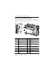
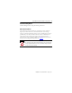
ControlNet Foundation Fieldbus Linking Device Parts Illustration of the Fieldbus Linking Device The sample illustration shows the parts that comprise the 1757-FFLDC linking device, which links Rockwell Automation products on ControlNet and FOUNDATION Fieldbus products on H1 networks.
ControlNet Foundation Fieldbus Linking Device 7 Before You Begin Before you install the linking device, read and complete the following sections. WARNING This product contains a ControlNet daughtercard (CAM) that is not intended for removal. Any attempt to remove this CAM or to operate the CAM release mechanism may cause irreparable damage. If you insert or remove the CAM while host power is on, an electrical arc can occur. This could cause an explosion in hazardous location installations.
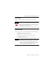
ControlNet Foundation Fieldbus Linking Device Set the ControlNet Node Address WARNING When you change switch settings while power is on, an electrical arc can occur. This could cause an explosion in hazardous location installations. Be sure that power is removed or the area is nonhazardous before proceeding. Use a small screwdriver to set the module’s ControlNet node address switches. 9 01 456 23 10’s digit 78 Example shows ControlNet node address switches set to 15.
ControlNet Foundation Fieldbus Linking Device 9 Install the Linking Device Install the linking device by using the following instructions. Mount the Linking Device Most applications require installation in an industrial enclosure (Pollution Degree 2) to reduce the effects of electrical interference (Over Voltage Category II) and environmental exposure.
ControlNet Foundation Fieldbus Linking Device Product Dimensions Dimension Measurement Height (A) 138 mm (5.43 in.) Width (B) 168 mm (6.62 in.) Depth (C) 87 mm (3.43 in.) A B C 43481-C Mount on a DIN Rail The linking device DIN-rail latch locks in the open position so that the linking device can be easily attached to or removed from the DIN rail. The maximum extension of the latch is 15 mm (0.67 in.) in the open position. You need a screwdriver to remove the linking device.
ControlNet Foundation Fieldbus Linking Device 11 Do these steps to install your linking device on a DIN rail. 1. Verify that the placement of the linking device on the DIN rail allows for 50 mm (2 in.) of space on all sides for adequate ventilation and 75 mm (3 in.) of space on the left side of the module if straight ControlNet taps are used. 2. Hook the top slot over the DIN rail as shown in the illustration. 3.
ControlNet Foundation Fieldbus Linking Device Mount on a Panel Do these steps to install your linking device on a panel. 1. Verify that the placement of the linking device allows for 50 mm (2 in.) of space on all sides for adequate ventilation and 75 mm (3 in.) of space on the left side of the module if straight ControlNet taps are used. 2. Use the following illustrations to mount the linking device to a panel by using #8 or M4 screws tightened to 1.1…1.8 N•m (10…16 lb•in). All dimensions are in mm (in.
ControlNet Foundation Fieldbus Linking Device 13 Wiring the Linking Device To wire the linking device, complete the following sections. Wire Requirements The FOUNDATION Fieldbus recommendation for the cable connecting fieldbus devices is Type A, 0.8 mm2 (18 AWG) shielded, twisted-pair wire. It is important to calculate how the planned topology for your fieldbus segment, selected wiring, supplied power, and intended mix of fieldbus devices may impact the overall performance of a fieldbus network.
ControlNet Foundation Fieldbus Linking Device Network Access Port The ControlNet network access port (NAP) provides a temporary connection for programming and troubleshooting purposes to a ControlNet communication card, for example, the 1784-PCIC, 1784-PCICS, 1784-U2CN, and 1784-PCC cards. The 1784-PCC card is not supported by RSFieldbus software, but RSFieldbus software can be used with the 1784-PCIC, 1784-PCICS, and 1784-U2CN cards to configure the 1757-FFLDC and FOUNDATION Fieldbus devices.
ControlNet Foundation Fieldbus Linking Device 15 H1 Terminal Block WARNING ATTENTION IMPORTANT When you connect or disconnect the removable terminal block (RTB) with field side power applied, an electrical arc can occur. This could cause an explosion in hazardous location installations. Be sure that power is removed or the area is nonhazardous before proceeding. Be careful when stripping wires. Wire fragments that fall into the linking device could cause damage.
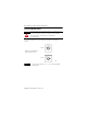
ControlNet Foundation Fieldbus Linking Device H1 Terminal Block Layout (catalog number 1757-FFLDC4 shown) + - + - + - + H1-1 + - + - + - + - H1-2 H1-3 H1-4 Power and Grounding If you connect or disconnect wiring while the field side power is on, an electrical arc can occur. This could cause an explosion in hazardous location installations. Be sure that power is removed or the area is nonhazardous before proceeding. WARNING ATTENTION Do not exceed 3 m (9.
ControlNet Foundation Fieldbus Linking Device 17 Install the EDS File Installing the electronic data sheet (EDS) file lets you schedule the linking device on the ControlNet network with RSNetworx for ControlNet software. The EDS file can be uploaded directly from the linking device. This feature lets you register the EDS file for your device from within RSLinx software by following the steps listed below. 1. Open RSLinx software, and browse for the linking device. 2.
ControlNet Foundation Fieldbus Linking Device Linking Device Reset Types Reset Type Description How Information Found In Reset configuration This restarts the linking device and deletes all downloaded fieldbus configurations. The linking device retains its network configuration and web page password information through this reset.
ControlNet Foundation Fieldbus Linking Device 19 Linking Device Reset Types Reset Type Description How Information Found In Reset/delete function blocks This deletes all blocks in the linking device except for the Resource Block. All Resource Block parameters are reset to factory default, including the tag name.
ControlNet Foundation Fieldbus Linking Device Reset to Factory Default The factory-default reset sets the linking device’s Ethernet network configuration to use the static IP address of 192.168.1.10, resets the web page user name and password, resets all services (for example, web services), and clears all downloaded fieldbus configuration. To complete a factory-default reset, complete the steps below. 1.
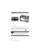
ControlNet Foundation Fieldbus Linking Device 21 Status Indicators Use the information in the following table to interpret the status indicators. 1757-FFLDC4 1757-FFLDC2 43574 Module Status Indicators Indicator Status Description H1 Off The H1 channel is inactive. Verify that the linking device is connected to the H1 network. Flashing green The linking device H1 channel is active. STATUS (module) Off No power - Module does not have 24V DC power. Flashing green Standby - Module not configured.
ControlNet Foundation Fieldbus Linking Device Module Status Indicators Indicator Status Description BATT (battery) Off Normal operation. Flashing red Jumper is missing (or not seated on the two rightmost pins), or the battery is low or dead.(1) NS (network status) Off Not powered. Flashing green No connections to the Logix blocks in the controller or to the Logix blocks in the linking device. • Verify physical connection by using the ControlNet status indicators.
ControlNet Foundation Fieldbus Linking Device 23 ControlNet Status Indicators 44427 IMPORTANT When you connect the module to a ControlNet network by using only the network access port (NAP), the status indicators are not accurate. ControlNet Network Troubleshooting (A AND B) AND Off Cause Action No power None or apply power to the linking device. Faulted ControlNet interface • Cycle power to the linking device.
ControlNet Foundation Fieldbus Linking Device ControlNet Channel Troubleshooting (A OR B) Cause Action Off Channel disabled Use RSNetWorx for ControlNet software to configure the ControlNet network for redundant media, if required. Solid green Normal operation None. Flashing green/off Temporary network errors OR • Check media for broken cables, loose connectors, or missing terminators.
ControlNet Foundation Fieldbus Linking Device 25 Specifications 1757-FFLDC2, 1757-FFLDC4 - Technical Specifications Attribute Value Physical interfaces 2 or 4 H1 FOUNDATION Fieldbus interfaces 1 redundant media ControlNet interface Number of H1 networks(1) per linking device 2 for 1757-FFLDC2 linking device, 4 for 1757-FFLDC4 linking device Number of fieldbus devices per H1 network, max 16 (8…10 recommended) Number of fieldbus devices per linking device, max 32 for the 1757-FFLDC2 linking device 6
ControlNet Foundation Fieldbus Linking Device 1757-FFLDC2, 1757-FFLDC4 - Technical Specifications Attribute Value Wire size DC power connection 0.2... 1.5 mm2 (26...16 AWG) solid or stranded copper wire rated at 75 °C (167 °F) or greater 1.2 mm (3/64 in.) insulation max Fieldbus connections 0.8 mm2 (18 AWG) solid or stranded shielded twisted pair copper wire rated at 75 °C (167 °F) or greater 1.2 mm (3/64 in.
ControlNet Foundation Fieldbus Linking Device 27 1757-FFLDC2, 1757-FFLDC4 - Environmental Specifications Attribute Value Temperature, operating 0…60 °C (32…140 °F) IEC 60068-2-1 (Test Ad, Operating Cold), IEC 60068-2-2 (Test Bd, Operating Dry Heat), IEC 60068-2-14 (Test Nb, Operating Thermal Shock) Temperature, nonoperating -40…85 °C (-40…185 °F) IEC 60068-2-1 (Test Ab, Unpackaged Nonoperating Cold), IEC 60068-2-2 (Test Bb, Unpackaged Nonoperating Dry Heat), IEC 60068-2-14 (Test Na, Unpackaged Nonope
ControlNet Foundation Fieldbus Linking Device 1757-FFLDC2, 1757-FFLDC4 - Environmental Specifications Attribute Value EFT/B immunity ±2 kV at 5 kHz on shielded fieldbus ports ±2 kV at 5 kHz on ControlNet ports IEC 61000-4-4 Surge transient immunity IEC 61000-4-5 Conducted RF immunity IEC 61000-4-6 Magnetic field immunity ±2 kV line-earth (CM) on shielded fieldbus ports ±2 kV line-earth (CM) on ControlNet ports 10V rms with 1 kHz sine-wave 80% AM from 150 kHz…80 MHz on ControlNet and shielded fieldb
ControlNet Foundation Fieldbus Linking Device 29 1757-FFLDC2, 1757-FFLDC4 - Certifications(1) Certification(2) Value Ex European Union 94/9/EC ATEX Directive, compliant with: • EN 60079-15; Potentially Explosive Atmospheres, Protection "n" • EN 60079-0; General Requirements • II 3 G Ex nA nL IIC CI ControlNet Int'l conformance tested to ControlNet specifications FF FOUNDATION Fieldbus H1 CTK Registered (1) When the product is marked. (2) See the Product Certification link at http://www.ab.
ControlNet Foundation Fieldbus Linking Device Additional Resources These documents contain additional information concerning related Rockwell Automation products. Resource Description ControlNet FOUNDATION Fieldbus Linking Device User Manual, publication 1757-UM011 Provides information on using the 1757-FFLDC linking device and the associated web pages. RSFieldbus Installation Guide, publication RSFBUS-IN001 Provides details on how to install the RSFieldbus software.
ControlNet Foundation Fieldbus Linking Device 31 The following FOUNDATION Fieldbus Specification documents contain information that you may find helpful as you read this manual. Resource Description FOUNDATION Fieldbus System Engineering Guidelines at http://www.fieldbus.org, publication AG-181 Provides the design, specification, installation, configuration, commissioning, and maintenance for a FOUNDATION Fieldbus-based control system.
Rockwell Automation Support Rockwell Automation provides technical information on the Web to assist you in using its products. At http://www.support.rockwellautomation.com you can find technical manuals, a knowledge base of FAQs, technical and application notes, sample code and links to software service packs, and a MySupport feature that you can customize to make the best use of these tools.