AIC+ Advanced Interface Converter Catalog Number 1761-NET-AIC User Manual
Important User Information Solid state equipment has operational characteristics differing from those of electromechanical equipment. Safety Guidelines for the Application, Installation and Maintenance of Solid State Controls (publication SGI-1.1 available from your local Rockwell Automation sales office or online at http://literature.rockwellautomation.com) describes some important differences between solid state equipment and hard-wired electromechanical devices.
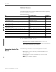
Summary of Changes The information below summarizes the changes to this manual since the last printing. To help you find new and updated information in this release of the manual, we have included change bars as shown to the right of this paragraph. 3 Topic Page Updated publication list 4 Ordering publications 4 Processor/cable compatibility 16...
Summary of Changes Publication 1761-UM004B-EN-P - June 2006
Table of Contents Preface Who Should Use This Manual . . . Purpose of This Manual. . . . . . . . Additional Resources . . . . . . . Conventions Used in This Manual . . . . . . . . . . . . . . . . . . . . . . . . . . . . . . . . . . . . . . . . . . . . . . . . . . . . . . . . . . . . . . . . . . . . . . . . . . . . . . . . . . . . 3 3 4 4 Chapter 1 Product Overview Description . . . . . . . . . . . . . . . . . . . . . . . . . . . . . . . . . . . . . . 5 Operation Modes . . . . . . . .
ii Table of Contents Appendix A Specifications and Dimensions General Specifications . . . . . . . . . . . . . . . . . . . Hardware Handshaking . . . . . . . . . . . . . . . Auto Transmit Delay (turnaround time) per Communication Rate . . . . . . . . . . . . . . . . . Mounting Template . . . . . . . . . . . . . . . . . . Index Publication 1761-UM004B-EN-P - June 2006 . . . . . . . . . . 33 . . . . . . . . . . 34 . . . . . . . . . . 35 . . . . . . . . . .
Preface Read this preface to familiarize yourself with the rest of the manual. This preface covers the following topics. • Who should use this manual • Purpose of this manual • Conventions used in this manual Who Should Use This Manual Use this manual if you are responsible for designing, installing, programming, or troubleshooting control systems that use Allen-Bradley Small Logic controllers.
4 Preface Additional Resources The following documents contain additional information regarding Rockwell Automation products.
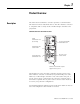
Chapter 1 Product Overview Description The AIC+ advanced interface converter provides a communication link between various networked devices. The AIC+ interface converter is compatible with a variety of SLC and MicroLogix controllers and peripherals.
6 Product Overview The communication-rate selector switch is used to match the communication rate filter of the AIC+ interface converter to the network communication rate. This switch does not change the network communication rate and is normally left in the AUTO position. In high noise environments, the communication-rate selector switch should be taken out of the AUTO mode and set to the same communication rate as the network.
Product Overview 7 Node Address Identification There is no node address associated with the network port. The node address is configured in the device connected with this port. The node address is configured in the device connected with this port. Use this area to mark the node address of each connection.
8 Product Overview Publication 1761-UM004B-EN-P - June 2006
Chapter 2 Installation and Wiring Compliance to European Union Directives If this product has the CE mark it is approved for installation within the European Union and EEA regions. It has been designed and tested to meet the following directives. EMC Directive This product is tested to meet Council Directive 89/336/EEC Electromagnetic Compatibility (EMC) and the following standards, in whole or in part, documented in a technical construction file.
10 Installation and Wiring Safety Considerations This equipment is suitable for use in Class I, Division 2, Groups A, B, C, D, or nonhazardous locations only. ATTENTION Explosion Hazard — Substitution of components may impair suitability for Class I, Division 2. Do not replace components or disconnect equipment unless power is switched off and the area is known to be nonhazardous.
Installation and Wiring Mount the AIC+ Advanced Interface Converter 11 The AIC+ interface converter can be mounted in the vertical or horizontal position. There are no spacing requirements except as necessary for DIN-rail latch movement. Mount to a DIN Rail Follow these steps to install your interface converter. 1. Mount your DIN rail. 2. Snap the DIN-rail latch into the closed position. 3. Hook the top slot over the DIN rail. Side View DIN Rail Latch 4.
12 Installation and Wiring Side View DIN Rail Mount to a Panel Follow these instructions to mount your AIC+ interface converter to a panel. 1. Remove the mounting template from this document. 2. Secure the template to the mounting surface. 3. Drill holes through the template. 4. Remove the mounting template. 5. Mount the AIC+ interface converter.
Installation and Wiring Wire the AIC+ Advanced Interface Converter 13 This section provides power supply wiring and network port wiring information. Wire the Power Supply ATTENTION EXPLOSION HAZARD — An external power supply must be used in Class I, Division 2 applications and the dc power-source selector switch must be in the EXTERNAL position before connecting the power supply to the AIC+ interface converter.
14 Installation and Wiring Wire to the Network Ports Use these instructions for wiring Belden cable. Attach the RS-485 Connector to the Communication Cable IMPORTANT A daisy-chained network is recommended. Other chained networks are not recommended. Daisy-chain Network Belden #3106A or #9842 Belden #3106A or #9842 Belden #3106A or #9842 Connector Connector Connector Incorrect Attach the connector to the Belden #3106A or #9842 cable as shown below.
Installation and Wiring 15 The table below shows connections for Belden #3106A. Belden #3106A Cable For This Wire/Pair Connect This Wire To This Terminal Shield/Drain Non-jacketed Terminal 2 – Shield Blue Blue Terminal 3 – (Common) White/Orange White with Orange Stripe Terminal 4 – (Data B) Orange with White Stripe Terminal 5 – (Data A) The table below shows connections for Belden #9842.
16 Installation and Wiring Cable Choices This section provides information that will help you determine the appropriate cable for your application. 1761-CBL-AC00 and 1747-CP3 Cable 1747-CP3 1761-CBL-AC00 1761-CBL-AC00 and 1747-CP3 Cable Cable Length Connects from 1747-CP3, 1761-CBL-AC00 Publication 1761-UM004B-EN-P - June 2006 3 m (9.8 ft), SLC 5/03, SLC 5/04, or SLC 5/05 45 cm (17.7 in.
Installation and Wiring 17 1761-CBL-AS03 and 1761-CBL-AS09 Cable 1761-CBL-AS09 1761-CBL-AS03 1761-CBL-AS03 and 1747-CBL-AS09 Cable Cable Length Connects from to AIC+ Interface Converter 1761-CBL-AS03, 3 m (9.8 ft), SLC 500 Fixed, SLC 5/01, SLC 5/02, 1761-CBL-AS09 9.9 m (29.
18 Installation and Wiring 1761-CBL-AP00 and 1761-CBL-PM02 Cable 1761-CBL-PM02 (1) 1761-CBL-AP00 1761-CBL-AP00 and 1761-CBL-PM02 Cable Cable 1761-CBL-AP00, 1761-CBL-PM02(1) Publication 1761-UM004B-EN-P - June 2006 Length 45 cm, (17.7 in.), 2m (6.
Installation and Wiring 19 User-supplied Cable User-supplied Cable User-supplied Cable Cable Straight through 9 pin Recommended User-supplied Components Length Connects — from to AIC+ Interface Converter Modem or other communication device RS-232 (DB-9, DTE) communication port These components can be purchased from your local electronics supplier. User-supplied Components Component Recommended Model External power supply and chassis ground Power supply rated for 20.4...28.
20 Installation and Wiring Ports Pin # DB-9 RS-232 RS-232 (8-pin mini-DIN) Communication Port(1) (1761-CBL-PM02 cable) Port 3 DH-485 Connector 1 Received line signal detector (DCD) Not applicable Chassis ground 2 Received data (RxD) Signal common (GRD) Cable shield 3 Transmitted data (TxD) Request to send (RTS) Signal ground 4 DTE ready (DTR) Received data (RxD) DH-485 data B 5 Signal common (GRD) Same state as port 1’s DCD signal DH-485 data A 6 DCE ready (DSR) Clear to send (CT
Chapter 3 Network Connections Network Diagrams This chapter provides various network connections. The item number provided in the Communication Port table corresponds to the designated port on the AIC+ advanced interface converter shown in each illustration.
22 Network Connections Components Replaced by the AIC+ Interface Converter The AIC+ interface converter replaces the combination of a 1747-PIC interface converter and 1747-AIC isolated link coupler in most applications.
Network Connections 23 DH-485 Network with SLC 5/03 and SLC 5/04 Processors and a PC DH-485 Network with SLC 5/03 and SLC 5/04 Processors and a PC PC SLC 5/03 or SLC 5/04 Processor APS 24V dc Power Connection from Processor Channel 0 1761-CBL-AP00 or 1761-CBL-PM02 Cable 1761-CBL-AP00 or 1761-CBL-PM02 Cable 3 AIC+ Converter 3 2 1 SLC DH-485 Network 1747-CP3 or 1761-CBL-AC00 Cable 1747-AIC Isolated Link Coupler SLC 5/02 Processor 1 1747-CP3 or 1761-CBL-AC00 Cable 2 AIC+ Converter 24V dc (user s
24 Network Connections DH-485 Network with a MicroLogix 1000 Controller DH-485 Network with a MicroLogix 1000 Controller MicroLogix 1000 Processor (series C or later) PC Connection from Port 1 or Port 2 to MicroLogix 1000 Processor 1761-CBL-AM00 or 1761-CBL-HM02 Cable AIC+ Converter 2 3 1761-CBL-AP00 or 1761-CBL-AP00 or 1761-CBL-PM02 Cable 1761-CBL-PM02 Cable 3 1 1 24V dc (User supply needed if using RS-232 (DB-9, DTE) com port.
Network Connections 25 Networked Operator-interface Device and MicroLogix Controller Networked Operator-interface Device and MicroLogix Controller PanelView 550 Operator Interface PC RS-232 Port NULL Modem Adapter Connection from NULL Modem Adapter 1761-CBL-AP00 or 1761-CBL-PM02 Cable 1761-CBL-AP00 or 1761-CBL-PM02 Cable AIC+ Converter 2 3 1 1747-CP3 or 1761-CBL-AC00 Cable AIC+ Converter 3 2 1 1747-CP3 or 1761-CBL-AC00 Cable 24V dc (user supplied) 24V dc (user supplied) 3 SLC DH-485 Network
26 Network Connections Networks Using Ganged Converters Networks Using Ganged Converters DH-485 Network with PanelView Interface PanelView Interface 1761-CBL-AM00 or 1761-CBL-HM02 Cable RJ45 Port PC 1761-CBL-AS09 or 1761-CBL-AS03 Cable 3 2 3 AIC+ Converter 2 AIC+ Converter 1 24V dc 24V dc (user supplied) (user supplied) 1747-CP3 or 1761-CBL-AC00 Cable DH-485 Network SLC 500 Fixed Controller RJ45 Port 24V dc power 1761-CBL-AS09 or 1761-CBL-AS03 Cable 1761-CBL-AM00 or 1761-CBL-HM02 Cable 3 AIC
Network Connections 27 Network Extended to 2438 m (8000 ft) Network Extended to 2438 m (8000 ft) DH-485 Network 1219 m (4000 ft), Maximum Extended DH-485 network 2438 m (8000 ft), maximum and 32 nodes total. 1761-CBL-AM00 or 1761-CBL-HM02 Cable 3 3 2 AIC+ Converter 24V dc (User supplied or from 24V dc terminals on SLC controller.) 2 AIC+ Converter 24V dc (User supplied or from 24V dc terminals on SLC controller.
28 Network Connections DF1 Master-slave Network with Modem DF1 Master-slave Network with Modem SLC 5/03 Processor SLC 5/03 Processor CH0 DF1 Master 3 1761-CBL-AP00 or 1761-CBL-PM02 Cable 2 Radio Modem or Lease Line AIC+ Converter 1 SLC 5/03 processor CH0 DF1 Slave 3 1 1761-CBL-AP00 or 1761-CBL-PM02 Cable 1747-CP3 or 1761-CBL-AC00 Cable AIC+ Converter 2 1 Straight 9...25 Pin Cable SLC 5/03 Processor CH0 DF1 Slave 3 2 1761-CBL-AP00 or 1761-CBL-PM02 Cable AIC+ Converter Straight 9...
Network Connections 29 Avoid Incorrect Connections Incorrect Connections DH-485 Network 1747-AIC Isolated Link Coupler 1761-CBL-AS09 or 1761-CBL-AS03 Cable AIC+ Converter 3 1761-CBL-AS09 or 1761-CBL-AS03 Cable 1747-AIC Isolated Link Coupler DH-485 Network SLC 5/03 Processor IMPORTANT In this configuration, the cable will fit but not function properly.
30 Network Connections Publication 1761-UM004B-EN-P - June 2006
Chapter 4 Interpret the LED Indicators Diagnostics LED Indicators and Selector Switch TX RS-485 LED Indicator TX RS-232 (8-pin mini-DIN) LED Indicator TX RS-232 (9-pin) LED Indicator PWR (Power) LED Indicator DC Power-source Selector Switch LED Indicator Status LED Indicator Status Condition TX RS-232 9-pin Flashing Transmitting. Off Receiving or idle. Flashing Transmitting. Off Receiving or idle. Flashing Transmitting. Off Receiving or idle. On Power OK.
32 Interpret the LED Indicators Publication 1761-UM004B-EN-P - June 2006
Appendix A Specifications and Dimensions General Specifications AIC+ Advanced Interface Converter - 1761-NET-AIC Attribute Value 24V dc Power Source Requirement 20.4...28.8V dc Current Draw 0...
34 Specifications and Dimensions Isolation Between All Ports and Power Supply Terminals RS-485 Communication Port (Phoenix Plug) RS-232 (8-pin mini-DIN) Communication Port RS-232 (DB-9, DTE) Communication Port Terminals for external 24V dc power supply and chassis ground. Hardware Handshaking To implement hardware handshaking, use cables that support the following signals. Signals Needed for Hardware Handshaking Signal Definition Function RTS active An input to AIC+ interface converter port.
Specifications and Dimensions 35 Auto Transmit Delay (turnaround time) per Communication Rate Communication Min Delay Rate (Kbps) (ms) Max Delay (ms) Typical Delay (ms) Pre-send Transmit Delay Setting (ms)(1) 600 7.3 15.0 10.8 16 1200 7.3 15.0 10.8 16 2400 5.5 11.2 8.1 12 4800 2.7 5.7 4.0 6 9600 1.3 2.8 2.0 3 14400 0.9 1.9 1.4 2 19200 0.6 1.4 1.0 2 AUTO 0.3 0.7 0.
36 Specifications and Dimensions Mounting Template 52.07 mm (2.05 in.) 107 mm (4.20 in.) 118 mm (4.64 in.) 27.7 mm (1.09 in.) Publication 1761-UM004B-EN-P - June 2006 Allow 15 mm (0.6 in.) clearance for DIN-rail latch movement during installation and removal.
Index A AIC+ Advanced Interface Converter compatibility with other devices 6 connect to a network 21 dimensions 36 LED indicators 31 mount 11 operating modes 6 product overview 5 specifications 33 wire 13 C cables 1747-CP3 16 1761-CBL-AC00 16 1761-CBL-AM00 17 1761-CBL-AP00 18 1761-CBL-AS03 17 1761-CBL-AS09 17 1761-CBL-HM02 17 1761-CBL-PM02 18 user-supplied 19 compliance to European Union directives 9 conventions used in this manual 4 D device compatibility 6 dimensions 36 DIN rail mount 11 H N networks
2 Index Publication 1761-UM004B-EN-P - June 2006
How Are We Doing? Your comments on our technical publications will help us serve you better in the future. Thank you for taking the time to provide us feedback. You can complete this form and mail (or fax) it back to us or email us at RADocumentComments@ra.rockwell.com Pub. Title/Type AIC+ Advanced Interface Converter User Manual Cat. No. 1761-NET-AIC Pub. No. 1761-UM004B-EN-P Pub. Date June 2006 Part No. Please complete the sections below.
PLEASE FASTEN HERE (DO NOT STAPLE) PLEASE FOLD HERE NO POSTAGE NECESSARY IF MAILED IN THE UNITED STATES BUSINESS REPLY MAIL FIRST-CLASS MAIL PERMIT NO.
Rockwell Automation Support Rockwell Automation provides technical information on the Web to assist you in using its products. At http://support.rockwellautomation.com, you can find technical manuals, a knowledge base of FAQs, technical and application notes, sample code and links to software service packs, and a MySupport feature that you can customize to make the best use of these tools.