Installation Instructions MicroLogix 1200 RTD/Resistance Input Module Catalog Number 1762-IR4 Topic Page Module Overview 2 Description 2 Module Installation 3 System Assembly 4 Mounting 4 Field Wiring Connections 7 I/O Memory Mapping 15 Specifications 19 North American Hazardous Location Approval 22 Additional Resources 23 Publication 1762-IN014B-EN-P - July 2013
MicroLogix 1200 RTD/Resistance Input Module Module Overview The 1762-IR4 module receives and stores digitally converted analog data from RTDs or other resistance inputs, such as potentiometers. The module supports connections from any combination of up to 4 RTDs or other resistance inputs. See the input specifications on page 20 for supported RTD and resistance types, their associated temperature ranges, and the analog input signal ranges that each channel supports.
MicroLogix 1200 RTD/Resistance Input Module 3 Module Installation 1762 I/O is suitable for use in an industrial environment when installed in accordance with these instructions. Specifically, this equipment is intended for use in clean, dry environments (Pollution degree 2(1)) and to circuits not exceeding Over Voltage Category II(2) (IEC 60664-1).(3) Prevent Electrostatic Discharge ATTENTION Electrostatic discharge can damage integrated circuits or semiconductors if you touch bus connector pins.
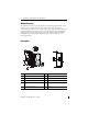
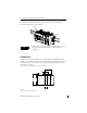
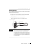
MicroLogix 1200 RTD/Resistance Input Module System Assembly The expansion I/O module is attached to the controller or another I/O module by means of a ribbon cable after mounting as shown below. TIP WARNING Use the pull loop on the connector to disconnect modules. Do not pull on the ribbon cable. EXPLOSION HAZARD • In Class I, Division 2 applications, the bus connector must be fully seated and the bus connector cover must be snapped in place.
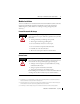
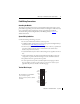
MicroLogix 1200 RTD/Resistance Input Module 5 Minimum Spacing Top Side 1762 I/O MicroLogix 1200 1762 I/O Side 1762 I/O Maintain spacing from enclosure walls, wireways, adjacent equipment, etc. Allow 50.8 mm (2 in.) of space on all sides for adequate ventilation, as shown: Bottom TIP ATTENTION The 1762 expansion I/O may be mounted horizontally only. During panel or DIN rail mounting of all devices, be sure that all debris (metal chips, wire strands, etc.) is kept from falling into the module.
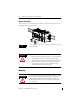
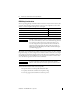
MicroLogix 1200 RTD/Resistance Input Module Use DIN rail end anchors (Allen-Bradley part number 1492-EA35 or 1492-EAH35) for environments with vibration or shock concerns. End Anchor End Anchor TIP For environments with extreme vibration and shock concerns, use the panel mounting method described below, instead of DIN rail mounting. Panel Mounting Use the dimensional template shown below to mount the module. The preferred mounting method is to use two M4 or #8 panhead screws per module. M3.
MicroLogix 1200 RTD/Resistance Input Module 7 Field Wiring Connections Grounding the Module This product is intended to be mounted to a well-grounded mounting surface such as a metal panel. Additional grounding connections from the module’s mounting tabs or DIN rail (if used) are not required unless the mounting surface cannot be grounded. Refer to Industrial Automation Wiring and Grounding Guidelines, Allen-Bradley publication 1770-4.1, for additional information.
MicroLogix 1200 RTD/Resistance Input Module RTD Wiring Considerations Since the operating principle of the RTD module is based on the measurement of resistance, take special care when selecting your input cable. For 2-wire or 3-wire configurations, select a cable that has a consistent impedance throughout its entire length. Configuration Recommended Cable 2-wire Belden™ 9501 or equivalent 3-wire — less than 30.48 m (100ft.) Belden™ 9533 or equivalent 3-wire — greater than 30.48 m (100 ft.
MicroLogix 1200 RTD/Resistance Input Module 9 RTD Wiring Configurations For a 3-wire configuration, the module can compensate for a maximum cable length associated with an overall cable impedance of 25 ohms.
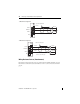
MicroLogix 1200 RTD/Resistance Input Module 3-Wire RTD Configuration Cable Shield (to Ground) RTD EXC RTD EXC Sense Sense Return Return EXC 2 SENSE 2 RTN 2 Belden 83503 or 9533 Shielded Cable NC 4-Wire RTD Configuration Cable Shield (to Ground) EXC 2 SENSE 2 RTN 2 NC RTD EXC RTD EXC Sense Sense Return Return Belden 83503 or 9533 Shielded Cable Leave one sensor wire open.
MicroLogix 1200 RTD/Resistance Input Module 11 2-Wire Potentiometer Interconnection Potentiometer Cable Shield (to Ground) RTD EXC EXC 2 SENSE 2 Return RTN 2 Belden 9501 Shielded Cable NC Cable Shield (to Ground) Potentiometer EXC 2 RTD EXC SENSE 2 RTN 2 NC TIP IMPORTANT Return Belden 9501 Shielded Cable The potentiometer wiper arm can be connected to either the EXC or return terminal, depending on whether you want increasing or decreasing resistance.
MicroLogix 1200 RTD/Resistance Input Module 3-Wire Potentiometer Interconnection Cable Shield (to Ground) Run RTD EXC and sense wires from the module to potentiometer terminal and tie terminal to one point. Potentiometer RTD EXC EXC 2 Sense SENSE 2 RTN 2 Return Belden 83503 or 9533 Shielded Cable NC Run RTD EXC and sense wires from the module to potentiometer terminal and tie terminal to one point.
MicroLogix 1200 RTD/Resistance Input Module 13 Labeling the Terminals A write-on label is provided with the module. Mark the identification of each terminal with permanent ink, and slide the label back into the door. Wiring the Finger-Safe Terminal Block ATTENTION Be careful when stripping wires. Wire fragments that fall into a module could cause damage when power is applied. Once wiring is complete, ensure the module is free of all metal fragments.
MicroLogix 1200 RTD/Resistance Input Module Wire Size and Terminal Screw Torque Each terminal accepts up to two wires with the following restrictions: Wire Type Wire Size Terminal Screw Torque Solid Cu-90 °C (194°F) #14…22 AWG 0.904 Nm (8 lb-in.) Stranded Cu-90 °C (194°F) #16…22 AWG 0.904 Nm (8 lb-in.) Wiring Input Devices to the 1762-IR4 ATTENTION Be careful when stripping wires. Wire fragments that fall into a module could cause damage at power up.
MicroLogix 1200 RTD/Resistance Input Module 15 To wire your sensor to the module, follow these steps: 1. At each end of the cable, strip some casing to expose the individual wires. 2. Trim the signal wires to 2-inch lengths. Strip about 3/16 inch (5 mm) of insulation away to expose the end of the wire. 3. At one end of the cable, twist the drain wire and foil shield together, bend them away from the cable, and apply shrink wrap.
MicroLogix 1200 RTD/Resistance Input Module Input Data File For each module, slot x, words 0 through 3 contain the analog values of the inputs. Words 4 and 5 provide sensor/channel status feedback. The input data file for each configuration is shown below.
MicroLogix 1200 RTD/Resistance Input Module Make these bit settings 15 14 13 12 11 10 9 8 7 6 5 4 Excitation Current Enable 0 Disable 1 Temperature Units Mode Open-circuit/ Broken Input 1.0 mA Input/Sensor Type 3 10 Hz 60 Hz 50 Hz 250Hz 500 Hz 1 kHz Cyclic Lead Compensation Filter Frequency To Select 0 0.
MicroLogix 1200 RTD/Resistance Input Module Raw/Proportional Engineering Units Engr. Units X 10 Scaled-for-PID Percent Range Make these bit settings 15 14 13 12 11 10 9 8 7 6 5 0 0 0 0 0 1 1 0 0 0 1 0 0 1 1 Enable 1 Disable 0 Enable Channel Data Format To Select 4 3 2 1 0 Module Configuration Word Word 4 of the configuration data file contains the Enable/Disable Cyclic Calibration bit, as shown in the table below.
MicroLogix 1200 RTD/Resistance Input Module 19 Specifications General Specifications Specification Value Dimensions, HxWxD 90 x 40 x 87 mm (3.54 x1.58 x 3.43 in.) height including mounting tabs is 110 mm (4.33 in.) Approximate Shipping Weight (with carton) 260 g (0.57 lbs.) Storage Temperature -40…85 °C (-40…185 °F) Operating Temperature 0…55 °C (+32…131 °F) Operating Humidity 5…95% non-condensing Operating Altitude 2000 m (6561 ft) Vibration Operating: 10…500 Hz, 5 g, 0.030 in. max.
MicroLogix 1200 RTD/Resistance Input Module Input Specifications Specification 1762-IR4 Input Types 100Ω Platinum 385 200Ω Platinum 385 500Ω Platinum 385 1000Ω Platinum 385 100Ω Platinum 3916 200Ω Platinum 3916 500Ω Platinum 3916 1000Ω Platinum 3916 Converter Type Sigma-Delta Resolution Input filter and configuration dependent. Refer to the MicroLogix 1200 RTD/Resistance Input Module User Manual, publication number 1762-UM003, for more information.
MicroLogix 1200 RTD/Resistance Input Module 21 Specification 1762-IR4 Input Channel Configuration Via configuration software screen or the user program (by writing a unique bit pattern into the module’s configuration file). Refer to your controller’s user manual to determine if user program configuration is supported. Calibration The module performs autocalibration on channel enable and on a configuration change between channels. You can also program the module to calibrate every five minutes.
MicroLogix 1200 RTD/Resistance Input Module North American Hazardous Location Approval The following modules are North American Hazardous Location approved: 1762-IR4 The following information applies when operating this equipment in hazardous locations: Informations sur l’utilisation de cet équipement en environnements dangereux: Products marked "CL I, DIV 2, GP A, B, C, D" are suitable for use in Class I Division 2 Groups A, B, C, D, Hazardous Locations and nonhazardous locations only.
MicroLogix 1200 RTD/Resistance Input Module 23 Additional Resources Publication Description MicroLogix 1200 Programmable Controllers User Manual, publication 1762-UM001. Information on installing, wiring, and operating a MicroLogix 1200 Programmable Controller MicroLogix 1200 Programmable Controllers Installation Instructions, publication 1762-IN006. Installation guide for the MicroLogix 1200 Programmable Controller.
Rockwell Automation Support Rockwell Automation provides technical information on the Web to assist you in using its products. At http://www.rockwellautomation.com/support/, you can find technical manuals, a knowledge base of FAQs, technical and application notes, sample code and links to software service packs, and a MySupport feature that you can customize to make the best use of these tools.