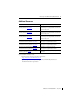
Installation Instructions MicroLogix 1762-OW16 Relay Output Module Catalog Number 1762-OW16 Table of Contents Topic Page Important User Information 2 North American Hazardous Location Approval 4 Additional Resources 5 Overview 6 Module Description 7 Mount the Module 8 Field Wiring Connections 11 Specifications 15
MicroLogix 1762-OW16 Relay Output Module Important User Information Solid state equipment has operational characteristics differing from those of electromechanical equipment. Safety Guidelines for the Application, Installation and Maintenance of Solid State Controls (Publication SGI-1.1 available from your local Rockwell Automation sales office or online at http://literature.rockwellautomation.
MicroLogix 1762-OW16 Relay Output Module 3 Environment and Enclosure ATTENTION This equipment is intended for use in a Pollution Degree 2 industrial environment, in overvoltage Category II applications (as defined in IEC 60664-1), at altitudes up to 2000 m (6562 ft) without derating.This equipment is considered Group 1, Class A industrial equipment according to IEC/CISPR 11.
MicroLogix 1762-OW16 Relay Output Module North American Hazardous Location Approval The following modules are North American Hazardous Location approved: 1762-OW16 The following information applies when operating this equipment in hazardous locations: Informations sur l’utilisation de cet équipement en environnements dangereux: Products marked "CL I, DIV 2, GP A, B, C, D" are suitable for use in Class I Division 2 Groups A, B, C, D, Hazardous Locations and nonhazardous locations only.
MicroLogix 1762-OW16 Relay Output Module 5 Additional Resources Resource Description MicroLogix 1100 Programmable Controllers User Manual, publication 1763-UM001. A more detailed description of how to install and use your MicroLogix 1100 programmable controller and expansion I/O system. MicroLogix 1200 Programmable Controllers User Manual, publication 1762-UM001. A more detailed description of how to install and use your MicroLogix 1200 programmable controller and expansion I/O system.
MicroLogix 1762-OW16 Relay Output Module Overview 1762 output module is suitable for use in an industrial environment when installed in accordance with these instructions. Specifically, this equipment is intended for use in clean, dry environments (Pollution degree 2(1)) and to circuits not exceeding Over Voltage Category II(2) (IEC 60664-1)(3). Install your module using these installation instructions.
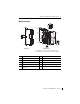
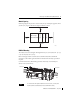
MicroLogix 1762-OW16 Relay Output Module 7 Module Description 5 1a 1a 2 9 6 4 4 2 7 3 3 1b 8 45164 Front view 2 45165 Left side view This equipment is sensitive to electrostatic discharge (ESD). Follow ESD prevention guidelines when handling this equipment.
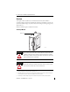
MicroLogix 1762-OW16 Relay Output Module Mount the Module General Considerations Most applications require installation in an industrial enclosure to reduce the effects of electrical interference and environmental exposure. Locate your controller as far as possible from power lines, load lines, and other sources of electrical noise such as hard-contact switches, relays, and AC motor drives.
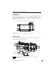
MicroLogix 1762-OW16 Relay Output Module 9 Module Spacing Maintain spacing from objects such as enclosure walls, wireways and adjacent equipment. Allow 50.8 mm (2 in.) of space on all sides for adequate ventilation, as shown: 1762 I/O 1762 I/O Side MicroLogix 1100/1200/1400 1762 I/O Top Side Bottom 44913 DIN Rail Mounting The module can be mounted using the following DIN rails: 35 x 7.5 mm (EN 50 022 - 35 x 7.5) or 35 x 15 mm (EN 50 022 - 35 x 15).
MicroLogix 1762-OW16 Relay Output Module Panel Mounting Use the dimensional template shown below to mount the module. The preferred mounting method is to use two M4 (#8) panhead screws per module. M3.5 (#6) panhead screws may also be used, but a washer may be needed to ensure a good mechanical contact. Mounting screws are required on every module. For more than 2 I/O modules: measure (number of modules - 1) x 40 mm (1.59 in.) 95 (3.74) 40.4 (1.59) 1762 I/O MicroLogix 1100/1200/1400 1762 I/O 100.
MicroLogix 1762-OW16 Relay Output Module 11 Field Wiring Connections Grounding the Module In solid-state control systems, grounding and wire routing helps limit the effects of noise due to electromagnetic interference (EMI). Run the ground connection from the ground screw of the controller to the ground bus prior to connecting any devices. Use AWG #14 wire. For AC-powered controllers, this connection must be made for safety purposes.
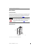
MicroLogix 1762-OW16 Relay Output Module Output Wiring Basic wiring of the 1762-OW16 is shown below. Basic Wiring to the 1762-OW16 Module OUT 0 CR L1 or +DC VAC-VDC 0 OUT 1 CR OUT 3 CR OUT 5 CR L2 or -DC OUT 2 OUT 4 CR OUT 6 CR OUT 7 VAC-VDC 1 L1 or +DC OUT 8 CR OUT 9 CR OUT 11 CR OUT 13 CR OUT 15 CR L2 or -DC OUT 10 OUT 12 CR OUT 14 A write-on label is provided with the module.
MicroLogix 1762-OW16 Relay Output Module 13 Wiring the Finger-Safe Terminal Block TIP Finger-safe cover not shown for clarity. When wiring the terminal block, keep the finger-safe cover in place. 1. Route the wire under the terminal pressure plate. You can use the stripped end of the wire or a spade lug. The terminals will accept a 6.35 mm (0.25 in.) spade lug. 2. Tighten the terminal screw making sure the pressure plate secures the wire. Recommended torque when tightening terminal screws is 0.
MicroLogix 1762-OW16 Relay Output Module I/O Memory Mapping Output Data File Word For each output module, the output data file contains the controller-directed state of the discrete output points. Bit positions 0…15 correspond to output terminals 0…15. Bit Position 15 14 13 12 11 10 9 8 7 6 5 4 3 2 1 0 0 w w w w w w w w w w w w w w w w w = write only 1762 Expansion I/O Addressing The addressing scheme for 1762 Expansion I/O is shown below.
MicroLogix 1762-OW16 Relay Output Module 15 Specifications General Specifications Attribute Value Dimensions, HxWxD 90 x 40.4 x 87 mm (3.54 x 1.59 x 3.43 in.) Height including mounting tabs is 110 mm (4.33 in.) Approximate Shipping Weight (with carton) 285g (0.63 lbs.) Relay Life - Electrical 100 x 10³ operations min.
MicroLogix 1762-OW16 Relay Output Module Output Specifications Attribute Value Isolated groups Group 1: Outputs 0…7 Group 2: Outputs 8…15 Output group to backplane isolation Verified by one of the following dielectric tests: 1836V AC for 1 sec. or 2596V DC for 1 sec. 265V AC working voltage (IEC Class 2 reinforced insulation) Output group to output group isolation Verified by one of the following dielectric tests: 1836V AC for 1 sec. or 2596V DC for 1 sec.
MicroLogix 1762-OW16 Relay Output Module 17 Environmental Specifications Attribute Value Temperature, operating IEC 60068-2-1 (Test Ad, Operating Cold), IEC 60068-2-2 (Test Bd, Operating Dry Heat), IEC 60068-2-14 (Test Nb, Operating Thermal Shock): -20... 65 °C (-4...
MicroLogix 1762-OW16 Relay Output Module Derating Chart for each output of the 1762-OW16 Relay Output Module POINTS 16 15 14 13 12 11 10 9 8 7 6 5 4 3 2 1 @24V DC* ML1400 ML1100 *24V bus voltage at typical condition = 24V DC.
MicroLogix 1762-OW16 Relay Output Module 19 Notes: Publication 1762-IN009C-EN-P - July 2013
Rockwell Automation Support Rockwell Automation provides technical information on the Web to assist you in using its products. At http://www.rockwellautomation.com/support/, you can find technical manuals, a knowledge base of FAQs, technical and application notes, sample code and links to software service packs, and a MySupport feature that you can customize to make the best use of these tools.