MicroLogix 1400 Embedded Web Server Bulletin 1766 Controllers User Manual
Important User Information Solid state equipment has operational characteristics differing from those of electromechanical equipment. Safety Guidelines for the Application, Installation and Maintenance of Solid State Controls (publication SGI-1.1 available from your local Rockwell Automation sales office or online at http://literature.rockwellautomation.com) describes some important differences between solid state equipment and hard-wired electromechanical devices.
Table of Contents Chapter 1 MicroLogix 1400 Embedded Web Server How to Use This Chapter . . . . . . . . . . . . . . . . . . . . . . Typical Applications . . . . . . . . . . . . . . . . . . . . . . . . . . Browser Requirements . . . . . . . . . . . . . . . . . . . . . . . . Connect the MicroLogix 1400 controller to the Network Navigate the MicroLogix 1400 Controller . . . . . . . . . . . . . . . . . . . . . . . . . . . . . . . . . . . . 3 3 3 4 6 . . . . . . . . . . . . . . . . . . . . . . . . . .
2 Table of Contents Notes: Publication 1766-UM002A-EN-P - November 2008
Chapter 1 MicroLogix 1400 Embedded Web Server How to Use This Chapter Rockwell Automation offers enhanced MicroLogix 1400 controllers for your EtherNet/IP control systems so you can monitor data remotely via web pages. This chapter shows how you can use a MicroLogix 1400 controller in your control system.
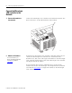
4 MicroLogix 1400 Embedded Web Server Connect the MicroLogix 1400 controller to the Network 1. Connect the module to the network. Connect the MicroLogix 1400 controller to the Ethernet network. The RJ-45 connector is on the left-hand side of the module. 44592 2. Obtain an IP address. For more information, see MicroLogix1400 Programmable Controllers User Manual 1766-UM001. By default, the MicroLogix 1400 controller is BOOTP enabled.
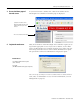
MicroLogix 1400 Embedded Web Server 3. Access the Home page of the web server. 5 In your web browser’s Address box, enter the IP address of the MicroLogix 1400 controller. The Home page is displayed. Specify the IP address of the MicroLogix 1400 controller in the Address window of your web browser. This is the controller’s Home page. 4. Log into the web server. Many of the features of the MicroLogix 1400 controller require you to log in with appropriate access.
6 MicroLogix 1400 Embedded Web Server Navigate the MicroLogix 1400 Controller Tabs across the top match the documents within a folder, as shown in the left navigation panel. Click folders to open and close additional levels of information. Click a document to display a web page showing specific information. Publication 1766-UM002A-EN-P - November 2008 You navigate the web server’s web pages by using the navigation panel on the left of the screen.
Chapter 2 Use Data Views to Access Controller Data How to Use This Chapter The MicroLogix 1400 controller provides access to the controller data table files. This chapter shows you how to set up views of data table files. Topic Overview of Data Views Page Overview of Data Views 7 Change an Access Group 8 Monitor Data Views and Data Table File 9 Change Data Table Files 10 Disable Web View 12 Data views give you the ability to read controller data via a browser interface.
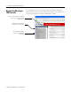
8 Use Data Views to Access Controller Data Change an Access Group Each data view contains a group of files that you want to monitor. Each MicroLogix 1400 controller can support multiple data views. One browser supports only one data view, so if you want to look at many data views, you need to run a corresponding number of browsers. You change an access group from the Data Views → New Data View page. 1.
Use Data Views to Access Controller Data Monitor Data Views and Data Table File 9 Use the Data Views → Data Views page to view existing data table files. Click the file name to view the data within a data table file. Data View Page The Data Views page displays a list of the data table files, their type, and size in elements for a connected MicroLogix 1400, as shown in the following example. Each file contains a hyperlink that takes you to the specific Data Views page for that file.
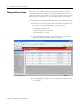
10 Use Data Views to Access Controller Data The available and default display formats depend on the data type of the file. Click Back to display the previous page. To refresh the data view, click Update. Change Data Table Files The data in the Data File Types such as Binary, Integer, Long, Float, and String can be changed. The Binary, Integer, and Long types support all the Display formats. You can edit Binary types by bit, and the Octal, Decimal, and Hexadecimal types by element.
Use Data Views to Access Controller Data 11 1. Change Display As to Binary, then the following screen appears. 2. Double-click the data you want to change, then the background color turns pink. 3. Enter a value and either press Enter or click an area in the screen, then a confirmation window appears.
12 Use Data Views to Access Controller Data 4. Click OK to change the value. The following screen appears when the value is successfully saved into the server. If the following screen appears, the value is not saved and the value returns to the original value. If you want to change the data in Decimal, click the pull-down menu to change the Display As to Decimal and follow the steps described. The steps also apply to the String type.
Use Data Views to Access Controller Data 13 Publication 1766-UM002A-EN-P - November 2008
14 Use Data Views to Access Controller Data Notes: Publication 1766-UM002A-EN-P - November 2008
Chapter 3 Monitor Diagnostics How to Use This Chapter This chapter describes the diagnostics presented on the user-oriented diagnostic pages. Topic MicroLogix 1400 Controller Diagnostics Page MicroLogix 1400 Controller Diagnostics 15 Diagnostic Overview 16 Network Settings 17 Network Status 18 The MicroLogix 1400 controller provides four diagnostic pages of user-oriented diagnostics.
16 Monitor Diagnostics Diagnostic Overview The Diagnostics → Diagnostic Overview page presents a summary of the current configuration and overall status of the MicroLogix 1400 controller. This summary includes: • Ethernet link. • Ethernet Connections.
Monitor Diagnostics Network Settings 17 The Diagnostics → Network Settings page presents a summary of the current Ethernet configuration for MicroLogix 1400. This summary includes: • Ethernet address details. Any fields not configured remain blank.
18 Monitor Diagnostics Network Status The Diagnostics → Network Status page presents a summary of the status of communication activity on the Ethernet network. This summary includes: • Ethernet network configuration. • packets sent and received over the Ethernet network. • frames sent and received over the Ethernet network.
Monitor Diagnostics This field 19 Specifies Multiple Collisions Successfully transmitted frames which experienced more than one collision Deferred Transmissions Frames for which first transmission attempt is delayed because the medium is busy Late Collisions Number of times a collision is detected later than 512 bit-times into the transmission of a packet Excessive Collisions Frames for which transmission fails due to excessive collisions MAC Transmit Errors Frames for which transmission fails
20 Monitor Diagnostics Notes: Publication 1766-UM002A-EN-P - November 2008
Chapter 4 Administrative Settings Server Settings Select Administrative Settings > Server Settings to customize some of the server settings of the module, as well as back up the file system on the web server module. You can: • customize server settings, including web home page. Customize Server Settings Select Administrative Settings > Server Settings to customize the web home page. In The Field Take This Action Web Home Page Select a home page of MicroLogix 1400 controller.
22 Administrative Settings Notes: Publication 1766-UM002A-EN-P - November 2008
Chapter 5 User Management How to Use This Chapter This chapter describes how to configure user access levels to different information on the module. Topic Page User Accounts and Privilege Classes 23 Configure Access Limits for Web Pages 24 Create User Accounts 25 Recover with Unknown Password 26 By assigning user accounts with different access levels, you can manage which users have access to view network configuration or have access to view and change data views.
24 User Management The access level determines which web pages the user can access. You configure access limits for individual web pages. Configure Access Limits for Web Pages Each page in the MicroLogix 1400 controller has one of these protection levels: • Administrator • Write • Read The protection levels are hierarchical. Administrator users can access Read protected pages.
User Management Create User Accounts 25 You need Administrator access to create and modify user accounts. You can create as many as 10 individual accounts. You manage accounts from the Administrative Settings → User Management → Edit Users page.
26 User Management Administrator acess group. The following screen, which shows only Read Access Group, appears when you log in with the guest account. Recover with Unknown Password Publication 1766-UM002A-EN-P - November 2008 Update the firmware using ControlFlash to initialize both user accounts and the access level of data view.
Chapter 6 Simple Web Pages MicroLogix 1400 controllers can supply Simple Web Pages in environments where communications status is an issue. These type of web pages only support HTML tags without graphic files. You can only monitor Ethernet configurations and data tables with these type of web pages.
28 Simple Web Pages Device Information The device information page displays a table with information about the Micrologix 1400 controller. The specific information displayed includes the controller model, series/revision and mode of the controller. Ethernet Configuration This page displays a table with information about the current Ethernet configuration parameters. Included are the module’s IP address, the subnet mask, gateway address, the Ethernet hardware address and whether BOOTP is enabled.
Simple Web Pages 29 secondary name server and the default domain name parameters, if configured. Diagnostic Information This section gives you access to the various diagnostic information screens that are available.
30 Simple Web Pages The diagnostic screens automatically refresh using a time which is configurable by the user and defaults to 15 seconds.
Simple Web Pages 31 controller. To view memory maps, login with a Read access group user account. Each file contains a hyperlink that takes you to the specific Data Table Monitor page for that file.
32 Simple Web Pages Table Monitor page appears, displaying the contents of the data table file you selected. The available and default display formats depend on the data type of the file. You can change the Display format and Refresh data every xx seconds fields by entering data in the text boxes and clicking the Change Parameters button. To change the refresh data function back to the default of 15 seconds, click the Default field. To disable the refresh data function, click the Disable button.
Chapter 7 User Provided Pages You can use a text editor to generate up to 8 user-provided web pages. Each page is stored in four consecutive ASCII files of the MicroLogix 1400 controller. The channel configuration feature of RSLogix 500/RSLogix Micro (version 8.10 or later) allows you to select the starting file number and the number of user pages to be stored, as shown in the following example: RSLogix 500/RSLogix Micro (version 8.
34 User Provided Pages • to reference a page on the same controller, specify a URL such as /user2.htm • to reference a page on another processor, specify a URL such as http://www.xxx.yyy.zzz/user2.htm, where www.xxx.yyy.
User Provided Pages 35 HTML Examples - the following example shows an HTML code segment with a short description of what you would see on a web browser: Examples Generating Custom Data Table Monitor Pages HTML Code Web Browser Displays Input image word I:0 the value of the first word of the input image table in the default format of decimal with bold type Timer T4:0 the values of the timer in T4:0 in the default format of a table Timer T4:0 the values
36 User Provided Pages You must always specify the basic file reference. Depending on which file is being referenced, file_number or file_element may be defaulted. If the file_type is I, O or S, the file_number does not need to be specified, but the file_element must be specified. If the file_type is not one of the three special files, the file_number must be specified and the file_element may default to zero (because the input, output and status files have fixed numbers).
User Provided Pages 37 7. Repeat this process for each user page file. 8. When all user page files have been imported, go online with your MicroLogix 1400 controller processor. 9. Select the User Provided Pages link to view the User Provided Pages menu, as shown in the following example: Click on the User Provided Page #X to display that specific page.
38 User Provided Pages Notes: Publication 1766-UM002A-EN-P - November 2008
Index A access group creating 8 access levels classes 23 access limits configuring 24 accessing typical application 3 administrative settings 21 Administrator access 24 authentication 23 B browser requirements 3 C change data table files 10 configure server settings 21 configuring access limits 24 user accounts 25 connecting 4 creating access group 8 D data table memory map 31 data views monitoring 9 overview 7 device information 28 diagnostic information 29 Diagnostic Overview 16 diagnostics diagnostic
40 Index Notes: Publication 1766-UM002A-EN-P - November 2008
How Are We Doing? Your comments on our technical publications will help us serve you better in the future. Thank you for taking the time to provide us feedback. You can complete this form and mail (or fax) it back to us or email us at RADocumentComments@ra.rockwell.com. Pub. Title/Type MicroLogix 1400 Embedded Web Server Cat. No. Bulletin 1766 Controllers Pub. No. 1766-UM002A-EN-P Pub. Date November 2008 Part No. Please complete the sections below.
PLEASE FASTEN HERE (DO NOT STAPLE) PLEASE FOLD HERE NO POSTAGE NECESSARY IF MAILED IN THE UNITED STATES BUSINESS REPLY MAIL FIRST-CLASS MAIL PERMIT NO.
Notes:
Notes:
Notes:
Rockwell Automation Support Rockwell Automation provides technical information on the Web to assist you in using its products. At http://support.rockwellautomation.com, you can find technical manuals, a knowledge base of FAQs, technical and application notes, sample code and links to software service packs, and a MySupport feature that you can customize to make the best use of these tools.