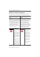
Installation Instructions MicroLogix 1400 Programmable Controllers Catalog Number(s) 1766-L32AWA, 1766-L32AWAA, 1766-L32BWA, 1766-L32BWAA, 1766-L32BXB, 1766-L32BXBA http://literature.rockwellautomation.com/idc/groups/literature/documents/in/1 766-in001_-mu-p.pdf FR Cette publication est disponible en français sous forme électronique (fichier PDF). Pour la télécharger, rendez-vous sur la page Internet indiquée ci-dessus. IT Questa pubblicazione è disponibile in Italiano in formato PDF.
Installation Instructions MicroLogix 1400 Programmable Controllers Catalog Number(s) 1766-L32AWA, 1766-L32AWAA, 1766-L32BWA, 1766-L32BWAA, 1766-L32BXB, 1766-L32BXBA Topic Page Important User Information 4 Additional Resources 7 Overview 8 Controller Description 9 Hazardous Location Considerations 11 Mount the Controller 13 Connect 1762 I/O Expansion Modules 18 Wire the Controller 19 Specifications 28
MicroLogix 1400 Programmable Controllers Important User Information Solid state equipment has operational characteristics differing from those of electromechanical equipment. Safety Guidelines for the Application, Installation and Maintenance of Solid State Controls (Publication SGI-1.1 available from your local Rockwell Automation sales office or online at http://literature.rockwellautomation.
MicroLogix 1400 Programmable Controllers 5 Environment and Enclosure ATTENTION This equipment is intended for use in a Pollution Degree 2 industrial environment, in overvoltage Category II applications (as defined in IEC publication 60664-1), at altitudes up to 2000 meters (6562 ft) without derating. This equipment is considered Group 1, Class A industrial equipment according to IEC/CISPR Publication 11.
MicroLogix 1400 Programmable Controllers North American Hazardous Location Approval The following modules are North American Hazardous Location approved: 1766-L32AWA, 1766-L32AWAA, 1766-L32BWA, 1766-L32BWAA, 1766-L32BXB, 1766-L32BXBA The following information applies when operating this equipment in hazardous locations: Informations sur l’utilisation de cet équipement en environnements dangereux: Products marked "CL I, DIV 2, GP A, B, C, D" are suitable for use in Class I Division 2 Groups A, B, C, D,
MicroLogix 1400 Programmable Controllers 7 Additional Resources Resource Description MicroLogix 1400 Programmable Controllers User Manual 1766-UM001 A more detailed description of how to install and use your MicroLogix 1400 programmable controller and expansion I/O system. MicroLogix 1400 Instruction Set Reference Manual 1766-RM001 A reference manual that contains data and function files, instruction set, and troubleshooting information for MicroLogix 1400.
MicroLogix 1400 Programmable Controllers Overview MicroLogix 1400 controllers are suitable for use in an industrial environment when installed in accordance with these instructions. Specifically, this equipment is intended for use in clean, dry environments (Pollution degree 2(1)) and with circuits not exceeding Over Voltage Category II(2) (IEC 60664-1)(3). AC powered products must be connected to the secondary of an isolating transformer. Install your controller using these installation instructions.
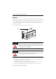
MicroLogix 1400 Programmable Controllers 9 Controller Description 1 2 3 4 5 6 7 ESC 1 OK 44514 13 12 11 Left side view 10 9 8 44515 Top view Description 1 Comm port 2 - 9-pin D-Shell RS-232C connector 2 Memory module (refer to MicroLogix 1400 Memory Module Installation Instructions, publication 1766-IN010 for instructions on installing the memory module).
MicroLogix 1400 Programmable Controllers Controller Input and Output Description Catalog Number Description Input Power 1766-L32BWA User Power Embedded Discrete I/O 24V DC 12 Fast 24V DC Inputs 8 Normal 24V DC Inputs 12 Relay Outputs 100/240V AC 1766-L32AWA 20 120V AC Inputs 12 Relay Outputs 1766-L32BXB 12 Fast 24V DC Inputs 8 Normal 24V DC Inputs 6 Relay Outputs 3 Fast DC Outputs 3 Normal DC Outputs None 24 V DC 1766-L32BWAA 24V DC 100/240V AC None 1766-L32BXBA 24V DC 12 Fast 24V DC In
MicroLogix 1400 Programmable Controllers 11 Hazardous Location Considerations This equipment is suitable for use in Class I, Division 2, Groups A, B, C, D or non-hazardous locations only. The following WARNING statement applies to use in hazardous locations. WARNING EXPLOSION HAZARD • Substitution of components may impair suitability for Class I, Division 2. • Do not replace components or disconnect equipment unless power has been switched off.
MicroLogix 1400 Programmable Controllers Environnements dangereux Cet équipement est conçu pour une utilisation en environnements dangereux de Classe I, Division 2, Groupes A, B, C, D ou non dangereux. La mise en garde suivante s’applique à utilisation en environnements dangereux. WARNING DANGER D’EXPLOSION • La substitution de composants peut rendre cet équipement impropre à une utilisation en environnement de Classe I, Division 2.
MicroLogix 1400 Programmable Controllers 13 Mount the Controller General Considerations Most applications require installation in an industrial enclosure to reduce the effects of electrical interference and environmental exposure. Locate your controller as far as possible from power lines, load lines, and other sources of electrical noise such as hard-contact switches, relays, and ac motor drives.
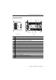
MicroLogix 1400 Programmable Controllers Mounting Dimensions C A 44516 B 1766-L32BWA, 1766-L32AWA, 1766-L32BXB, 1766-L32BWAA, 1766-L32AWAA, 1766-L32BXBA Dimension Height A 90 mm (3.5 in.) B 180 mm (7.087 in.) C 87 mm (3.43 in.) Controller Spacing The controller mounts horizontally, with the expansion I/O extending to the right of the controller. Allow 50 mm (2 in.) of space on all but the right side for adequate ventilation, as shown below.
MicroLogix 1400 Programmable Controllers 15 DIN Rail Mounting The maximum extension of the latch is 14 mm (0.55 in.) in the open position. A flat-blade screwdriver is required for removal of the controller. The controller can be mounted to EN50022-35x7.5 or EN50022-35x15 DIN rails. DIN rail mounting dimensions are shown below. B A C 44518 Dimension Height A 90 mm (3.5 in.) B 27.5 mm (1.08 in.) C 27.5 mm (1.08 in.) Follow these steps to install your controller on the DIN rail. 1.
MicroLogix 1400 Programmable Controllers 2. Holding the controller, pry downward on the latch until the latch locks in the open position. 3. Repeat steps 1 and 2 for the second DIN rail latch. 4. Unhook the top of the DIN rail slot from the rail. ESC OK Open Closed 44519 44520 Panel Mounting Mount to panel using #8 or M4 screws. Follow these steps to install your controller using mounting screws. 1. Remove the mounting template from inside the back cover of this document. 2.
MicroLogix 1400 Programmable Controllers 17 Using the Battery The MicroLogix 1400 controller is equipped with a replaceable battery (catalog number 1747-BA). The Battery Low indicator on the LCD display of the controller shows the status of the replaceable battery. When the battery is low, the indicator is set (displayed as a solid rectangle). This means that either the battery wire connector is disconnected, or the battery may fail within 2 days if it is connected.
MicroLogix 1400 Programmable Controllers 2. Secure the battery connector wires so that it does not block the 1762 expansion bus connector as shown below. Battery compartment Battery 1762 I/O expansion bus connector Battery wire connector Battery connector Battery wires twisted pair 44522 Connect 1762 I/O Expansion Modules ATTENTION Remove power from the system before installing or removing expansion I/O or damage to the controller may result. Connect 1762 I/O after mounting the controller. 1.
MicroLogix 1400 Programmable Controllers 19 3. Replace the cover as shown below. 44523 The MicroLogix 1400 controller is designed to support up to any seven 1762 expansion I/O modules. For detailed information on using expansion I/O, refer to the installation instructions for your expansion module. Wire the Controller The shading in the following terminal block illustrations indicates which terminal groups are tied to which commons.
MicroLogix 1400 Programmable Controllers 1766-L32BWA/L32BWAA Input Terminal Block IN0 COM 0 VAC L1 COM 1 IN2 IN1 IN3 VAC L2/N OUT0 IN5 IN6 OUT1 OUT2 Group 0 DC2 VAC Group 1 Group 2 IN8 IN9 OUT3 DC3 VAC COM 3 IN10 COM 2 IN4 DC1 VAC DC0 VAC IN7 IN11 Group 3 OUT5 IN17 IN14 IN16 OUT7 OUT8 OUT10 DC6 VAC OUT6 Group 4 IN15 IN12 VAC DC5 OUT4 DC4 VAC IN13 Group 5 OUT9 IN19 IN18 COM ANA COM ANA OUT11 IV0(+) IV2(+) IV1(+) IV3(+) OV1 OV0 Group 6 44524 Ou
MicroLogix 1400 Programmable Controllers 21 1766-L32BXB/L32BXBA Input Terminal Block IN0 COM 0 VDC +24 COM 1 IN2 IN1 IN3 VDC NEUT OUT0 IN5 IN7 IN6 OUT1 OUT2 DC1 VAC Group 0 Group 1 VDC2 OUT4 OUT3 COM 3 IN10 COM 2 IN4 DC0 VAC IN8 IN13 IN15 IN17 IN9 IN11 IN12 IN14 IN16 OUT6 COM 2 OUT8 OUT9 OUT10 OUT5 OUT7 Group 2 Wire Type DC3 VAC DC4 VAC Group 3 Group 4 DC5 VAC IV0(+) IN19 IN18 OUT11 COM ANA COM ANA IV2(+) IV1(+) IV3(+) OV1 OV0 Group 5 44526 Wire
MicroLogix 1400 Programmable Controllers Output Terminal Grouping Outputs Controller Output Group Description Voltage Terminal Output Terminal 1766-L32AWA 1766-L32AWAA Group 0 Isolated relay output VAC/DC0 OUT 0 Group 1 Isolated relay output VAC/DC1 OUT 1 Group 2 Isolated relay output VAC/DC2 OUT 2 Group 3 Isolated relay output VAC/DC3 OUT 3 Group 4 Isolated relay output VAC/DC4 OUT 4, OUT 5 Group 5 Isolated relay output VAC/DC5 OUT 6, OUT 7 Group 6 Isolated relay output
MicroLogix 1400 Programmable Controllers 23 Wiring Recommendation When wiring without spade lugs, keep the finger-safe covers in place. Loosen the terminal screw and route the wires through the opening in the finger-safe cover. Tighten the terminal screw, making sure the pressure plate secures the wire. Finger-safe cover 44527 ATTENTION Be careful when stripping wires. Wire fragments that fall into the controller could cause damage.
MicroLogix 1400 Programmable Controllers Spade Lug Recommendation The diameter of the terminal screw head is 5.5 mm (0.220 in.). The input and output terminals of the MicroLogix 1400 controller are designed for the following spade lugs. The terminals will accept a 6.35mm (0.25 in.) wide spade (standard for #6 screw for up to 14 AWG) or a 4 mm (metric #4) fork terminal.
MicroLogix 1400 Programmable Controllers 25 Grounding the Controller In solid-state control systems, grounding and wire routing helps limit the effects of noise due to electromagnetic interference (EMI). Run the ground connection from the ground screw of the controller to the ground bus prior to connecting any devices. Use AWG #14 wire. For AC-powered controllers, this connection must be made for safety purposes. You must also provide an acceptable grounding path for each device in your application.
MicroLogix 1400 Programmable Controllers The controller does not provide loop power for analog inputs. Use a power supply that matches the transmitter specifications as shown. The analog output can support a voltage function as shown in the following illustration.
MicroLogix 1400 Programmable Controllers 27 Minimizing Electrical Noise on Analog Channels Inputs on analog channels employ digital high-frequency filters that significantly reduce the effects of electrical noise on input signals. However, because of the variety of applications and environments where analog controllers are installed and operated, it is impossible to ensure that all environmental noise will be removed by the input filters.
MicroLogix 1400 Programmable Controllers Specifications General Specifications Description 1766-L32AWA 1766-L32AWAA Dimensions HxWxD 90 x 180 x 87 mm 3.5 x 7.087 x 3.43 in. Shipping weight 0.9 kg (2.0 lbs) Number of I/O 24 inputs (20 digital and 4 analog) and 14 outputs (12 digital and 2 analog) Power supply voltage 100…240V AC (-15%, +10%) @ 47…63 Hz Heat dissipation Refer to the MicroLogix 1400 Programmable Controllers User Manual, Publication 1766-UM001.
MicroLogix 1400 Programmable Controllers 29 Specifications for Inputs Digital Inputs Description On-state voltage range 1766-L32AWA 1766-L32AWAA 79…132 V AC 1766-L32BWA, 1766-L32BWAA, 1766-L32BXB, 1766-L32BXBA Inputs 0 through 11 (12 high-speed DC inputs) Inputs 12 and higher (8 standard DC inputs) 4.5…24V DC, Class 2 10…24V DC, Class 2 (4.5…26.4V DC @ 60°C/140°F) (4.5…30V DC @ 30°C/86°F) (10…26.4V DC @ 60°C/140°F) (10…30V DC @ 30°C/86°F) Off-state voltage range 0…20 V AC 0…1.
MicroLogix 1400 Programmable Controllers Analog Outputs Description 1766-L32AWAA, -L32BWAA, -L32BXBA Number of inputs 2 single-ended Voltage output range 0…10 V DC - 1 LSB Type of data 12 bit unsigned integer Step response 2.5 ms @ 95% Load range Voltage output 1 KΩ Output resolution 12 bit Analog output setting time 3 ms (max.) Overall Accuracy -20…60 °C (-4…140 °F) ±1.
MicroLogix 1400 Programmable Controllers Maximum Volts Amperes Make Break 240V AC 7.5 A 0.75 A 120V AC 15.0 A 1.5 A Amperes Continuous 31 Volt-Amperes Make Break 2.5 A 1800 VA 180 VA 2.5 A 1800 VA 180 VA 250V DC 0.11 A 1.0 A 28 VA 125V DC 0.22 A 1.0 A 28 VA 1766-L32BXB, 1766-L32BXBA FET Output Maximum output current (temperature dependent): FET Current per Point FET Total Current 2.0 8.0 1.75 6.0A , 30°C (86°F) 6.0 1.25 1.0 0.75A, 60°C (140°F) Valid Range 0.75 0.5 0.
MicroLogix 1400 Programmable Controllers Description General Operation High Speed Operation(1) (Output 2, 3 and 4 Only) Turn-On Time (maximum) 11 µs 28 ns Turn-Off Time (maximum) 89 µs 2.3 µs (1) Output 2, 3 and 4 are designed to provide increased functionality over the other FET outputs. Output 2, 3 and 4 may be used like the other FET transistor outputs, but in addition, within a limited current range, they may be operated at a higher speed.
MicroLogix 1400 Programmable Controllers 33 Working Voltage for 1766-L32BWA, 1766-L32BWAA Description Recommendation Power supply input to backplane isolation Verified by one of the following dielectric tests:1836V AC for 1 second or 2596V DC for 1 second Input group to backplane isolation and input group to input group isolation Verified by one of the following dielectric tests: 1100V AC for 1 second or 1697V DC for 1 second Output group to backplane Isolation Verified by one of the following diel
MicroLogix 1400 Programmable Controllers Environmental Specifications Description 1766-L32AWA 1766-L32AWAA Temperature, operating IEC 60068-2-1 (Test Ad, Operating Cold), IEC 60068-2-2 (Test Bd, Operating Dry Heat), IEC 60068-2-14 (Test Nb, Operating Thermal Shock): -20… 60 °C (-4…140 °F) Temperature, storage IEC 60068-2-1 (Test Ab, Unpackaged Non-operating Cold), IEC 60068-2-2 (Test Bb, Unpackaged Non-operating Dry Heat), IEC 60068-2-14 (Test Na, Unpackaged Non-operating Thermal Shock): -40…85 °C
MicroLogix 1400 Programmable Controllers Description 1766-L32AWA 1766-L32AWAA 1766-L32BWA 1766-L32BWAA Surge transient immunity IEC 61000-4-5: ±1 kV line-line(DM) and ±2 kV line-earth(CM) on AC power ports ±1 kV line-line(DM) and ±2 kV line-earth(CM) on signal ports ±1 kV line-earth(CM) on communications ports Conducted RF immunity IEC 61000-4-6: 10V rms with 1 kHz sine-wave 80% AM from 150 kHz…80 MHz Voltage variation IEC 6100-4-11: 60% dip for 10 periods on AC supply ports 30% dips for 25 periods
MicroLogix 1400 Programmable Controllers Publication 1766-IN001C-EN-P - October 2009
180.0 mm (7.087 in.) 25.81 mm (1.016 in.) 165.8 mm (6.528 in.) 0.164 DIN rail center line. Ligne médiane du rail DIN. Mittellinie der DIN-Schiene. Línea central del riel DIN. Linea centrale della guida DIN. linha de centro do trilho DIN. Expansion I/O Extension d'E/S E/A Erweiterungsmodule Espansione dei moduli I/O Expansión de E/S 100.06 mm (3.939 in.
INPUTS INPUTS 0 1 1 OUTPUTS 0 OUTPUTS 2 2 3 4 5 6 7 8 9 10 11 12 13 14 14 11 13 11 10 12 10 9 11 9 8 10 8 7 9 7 6 8 6 5 7 5 4 6 4 3 5 3 2 4 2 1 3 1 0 0 15 15 16 16 17 17 18 18 19 19 L32AWAA L32AWA
VAC L1 NC NC OUT 10 OUT 11 OUT 8 OUT 9 OUT 7 VAC DC6 VAC DC5 OUT 6 OUT 4 OUT 5 OUT 3 VAC DC4 OUT 2 VAC DC3 OUT 1 VAC DC2 OUT 0 VAC DC1 VAC L2/N VAC DC0 IN19 NC NC NC IN17 IN18 IN15 IN16 IN13 IN14 COM 3 IN12 IN10 IN11 IN8 IN9 IN7 COM 2 IN5 IN6 COM 1 IN4 IN2 IN3 IN0 IN1 1766-L32AWA 1766-L32AWA COM 0 OV1 OV0 COM ANA OUT 11 OUT 10 OUT 9 OUT 8 VAC DC6 OUT 7 OUT 6 VAC DC5 OUT 5 OUT 4 VAC DC4 OUT 3 VAC DC3 OUT 2 VAC DC2 OUT 1 VAC DC1 OUT 0 VAC DC0 IV0 COM ANA IN19 IN18
INPUTS INPUTS 0 1 1 OUTPUTS 0 OUTPUTS 2 2 3 4 5 6 7 8 9 10 11 12 13 14 14 11 13 11 10 12 10 9 11 9 8 10 8 7 9 7 6 8 6 5 7 5 4 6 4 3 5 3 2 4 2 1 3 1 0 0 15 15 16 16 17 17 18 18 19 19 L32BWAA L32BWA
VAC L1 NC NC OUT 10 OUT 11 OUT 8 OUT 9 OUT 7 VAC DC6 VAC DC5 OUT 6 OUT 4 OUT 5 OUT 3 VAC DC4 OUT 2 VAC DC3 OUT 1 VAC DC2 OUT 0 VAC DC1 VAC L2/N VAC DC0 IN19 NC NC NC IN17 IN18 IN15 IN16 IN13 IN14 COM 3 IN12 IN10 IN11 IN8 IN9 IN7 COM 2 IN5 IN6 COM 1 IN4 IN2 IN3 IN0 IN1 1766-L32BWA 1766-L32BWA COM 0 OV1 OV0 COM ANA OUT 11 OUT 10 OUT 9 OUT 8 VAC DC6 OUT 7 OUT 6 VAC DC5 OUT 5 OUT 4 VAC DC4 OUT 3 VAC DC3 OUT 2 VAC DC2 OUT 1 VAC DC1 OUT 0 VAC DC0 IV0 COM ANA IN19 IN18
INPUTS INPUTS 0 1 1 OUTPUTS 0 OUTPUTS 2 2 3 4 5 6 7 8 9 10 11 12 13 14 14 11 13 11 10 12 10 9 11 9 8 10 8 7 9 7 6 8 6 5 7 5 4 6 4 3 5 3 2 4 2 1 3 1 0 0 15 15 16 16 17 17 18 18 19 19 L32BXB L32BXBA
+24 VDC COM ANA OV0 OUT 10 OUT 11 OUT 9 VAC DC5 OUT 8 VAC DC4 COM 2 VAC DC3 OUT 6 OUT 7 OUT 4 OUT 5 OUT 2 OUT 3 OUT 1 VDC 2 OUT 0 VAC DC1 VDC NEUT VAC DC0 IN19 OV1 IV0 COM ANA IN17 IN18 IN15 IN16 IN13 IN14 COM 3 IN12 IN10 IN11 IN8 IN9 IN7 COM 2 IN5 IN6 COM 1 IN4 IN2 IN3 IN0 IN1 1766-L32BXBA 1766-L32BXBA COM 0 NC NC NC OUT 11 OUT 10 VAC DC5 OUT 9 VAC DC4 OUT 8 VAC DC3 COM 2 OUT 7 OUT 6 OUT 5 OUT 4 OUT 3 OUT 2 VDC 2 NC OUT 1 VAC DC1 IN19 OUT 0 VAC DC0 IN17 IN18
Publication 1766-IN001C-EN-P - October 2009
Rockwell Automation Support Rockwell Automation provides technical information on the Web to assist you in using its products. At http://support.rockwellautomation.com, you can find technical manuals, a knowledge base of FAQs, technical and application notes, sample code and links to software service packs, and a MySupport feature that you can customize to make the best use of these tools.