
Installation Instructions Owner manual


MicroLogix 1400 Programmable Controllers 9
Publication 1766-IN001C-EN-P - October 2009
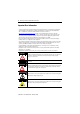
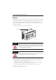
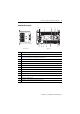
Controller Description
Description
1 Comm port 2 - 9-pin D-Shell RS-232C connector
2 Memory module (refer to MicroLogix 1400 Memory Module Installation Instructions, publication
1766-IN010
for instructions on installing the memory module).
3 User 24V (for 1766-L32BWA and 1766-L32BWAA only)
4 Input terminal block
5 LCD Display Keypad (ESC, OK, Up, Down, Left, Right)
6 Battery compartment
7 1762 expansion bus connector
8 Battery connector
9 Output terminal block
10 LCD Display
11 Indicator LED panel
12 Comm port 1 - RJ45 connector
13 Comm port 0 - 8-pin mini DIN RS-232C/RS-485 connector
1
ESC
OK
256 7
8
9101113 12
43
1
44515
44514
Left side view Top view