
Instruction Manual
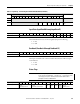
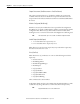
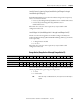
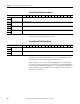
Table Of Contents
- 1769-UM006E-EN-P, Compact High-speed Counter Module User Manual
- Summary of Changes
- Table of Contents
- Preface
- 1 - Module Overview
- 2 - Module Operation
- 3 - Installation and Wiring
- 4 - Module Configuration, Output, and Input Data
- Configure the Module
- Configuration Array
- General Configuration Bits
- Filter Selection
- Program Mode and Program State Run
- Output Program Value (Out0ProgramValue through Out3ProgramValue)
- Output Fault Mode and Output Fault State Run
- Output Fault Value (Out0FaultValue through Out3FaultValue)
- Counter Maximum Count (CtrnMaxCount)
- Counter Minimum Count (CtrnMinCount)
- Counter Preset (CtrnPreset)
- Counter Hysteresis (CtrnHysteresis)
- Counter Scalar (CtrnScalar)
- Cyclic Rate Update Time (CtrnCyclicRateUpdateTime)
- Configuration Flags
- Range High Limit (Range0To11[n].HighLimit) and Range Low Limit (Range0To11[n].LowLimit)
- Range Output Control (Range0To11[n].OutputControl)
- Range Configuration Flags
- Output Array
- Output on Mask (OutputOnMask.0 through OutputOnMask.15)
- Output Off Mask (OutputOffMask.0 through OutputOffMask.15)
- Range Enable (RangeEn.0 through RangeEn.15)
- RBF - Reset Blown Fuse (ResetBlownFuse)
- Control Bits
- Range High Limit or Direct Write Value (Range12To15[n].HiLimOrDirWr)
- Range Low Limit (Range12To15[n].LowLimit)
- Range Output Control (Range12To15[n].OutputControl)
- Range Configuration Flags (12To15)
- Input Array
- Input State (InputStateA0 through InputStateZ1)
- Readback (Readback.0 through Readback.15)
- Status Flags
- Range Active (RangeActive.0 through RangeActive.15)
- Current Count (Ctr[n].CurrentCount)
- Stored Count (Ctr[n].StoredCount)
- Current Rate (Ctr[0].CurrentRate to Ctr[3].CurrentRate)
- Pulse Interval (Ctr[0].PulseInterval and Ctr[1].PulseInterval)
- Status Flags
- 5 - Diagnostics and Troubleshooting
- A - Specifications
- B - Program a 1769-HSC Module, CompactLogix Controller, and 845F Incremental Encoder with RSLogix 5000 Software
- C - Program a 1769-HSC Module, MicroLogix 1500 Controller, and 845F Incremental Encoder with RSLogix 500 Software
- D - Programming Quick Reference
- E - History of Changes
- Glossary
- Index
- Back Cover

102 Rockwell Automation Publication 1769-UM006E-EN-P - July 2013
Chapter 4 Module Configuration, Output, and Input Data
Output Overcurrent (Out0Overcurrent to Out3OverCurrent)
The output overcurrent bits are set (1) when the module is in an overcurrent
condition. These bits also show whether the output is latched off, because the
output remains in the off state and these bits remain on until the ResetBlownFuse
bit is used.
Module Configured (ModConfig)
Word 2, bit 5 is set by the module after it has accepted all of the configuration
data. When set (1), this bit confirms that the module received and accepted valid
configuration data. When reset (0), this bit indicates that the module still is
checking for errors or contains errors and the old configuration is still being used.
Invalid Output (InvalidOutput)
• 1 = an unused bit in the output array is set
• 0 = no unused bits in the output array are set
When this error occurs, the entire output array is rejected until an output array
that does not have this error is sent.
Error (GenError)
When this bit is set (1), it indicates one or more of the following errors for the
input array:
• OutnOvercurrent
• InvalidRangeLimitn
• InvalidCtrAssignToRangen
• InvalidOutput
• Ctr[n].Overflow
• Ctr[n].Underflow
• Ctr[n].InvalidDirectWrite
• Ctr[n].InvalidCounter
• Ctr[n].PresetWarning
where n indicates the counter number.
To determine which error has set the GenError bit, identify which bit is set. This
could be done by using a subroutine to examine these bits in the input array.
TIP
The module takes up to two seconds to validate configuration data.
TIP
Ctr[n].RateValid does not set the GenError bit.