
Instruction Manual
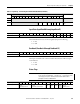
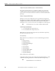
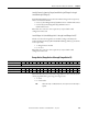
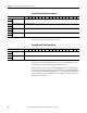
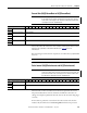
Table Of Contents
- 1769-UM006E-EN-P, Compact High-speed Counter Module User Manual
- Summary of Changes
- Table of Contents
- Preface
- 1 - Module Overview
- 2 - Module Operation
- 3 - Installation and Wiring
- 4 - Module Configuration, Output, and Input Data
- Configure the Module
- Configuration Array
- General Configuration Bits
- Filter Selection
- Program Mode and Program State Run
- Output Program Value (Out0ProgramValue through Out3ProgramValue)
- Output Fault Mode and Output Fault State Run
- Output Fault Value (Out0FaultValue through Out3FaultValue)
- Counter Maximum Count (CtrnMaxCount)
- Counter Minimum Count (CtrnMinCount)
- Counter Preset (CtrnPreset)
- Counter Hysteresis (CtrnHysteresis)
- Counter Scalar (CtrnScalar)
- Cyclic Rate Update Time (CtrnCyclicRateUpdateTime)
- Configuration Flags
- Range High Limit (Range0To11[n].HighLimit) and Range Low Limit (Range0To11[n].LowLimit)
- Range Output Control (Range0To11[n].OutputControl)
- Range Configuration Flags
- Output Array
- Output on Mask (OutputOnMask.0 through OutputOnMask.15)
- Output Off Mask (OutputOffMask.0 through OutputOffMask.15)
- Range Enable (RangeEn.0 through RangeEn.15)
- RBF - Reset Blown Fuse (ResetBlownFuse)
- Control Bits
- Range High Limit or Direct Write Value (Range12To15[n].HiLimOrDirWr)
- Range Low Limit (Range12To15[n].LowLimit)
- Range Output Control (Range12To15[n].OutputControl)
- Range Configuration Flags (12To15)
- Input Array
- Input State (InputStateA0 through InputStateZ1)
- Readback (Readback.0 through Readback.15)
- Status Flags
- Range Active (RangeActive.0 through RangeActive.15)
- Current Count (Ctr[n].CurrentCount)
- Stored Count (Ctr[n].StoredCount)
- Current Rate (Ctr[0].CurrentRate to Ctr[3].CurrentRate)
- Pulse Interval (Ctr[0].PulseInterval and Ctr[1].PulseInterval)
- Status Flags
- 5 - Diagnostics and Troubleshooting
- A - Specifications
- B - Program a 1769-HSC Module, CompactLogix Controller, and 845F Incremental Encoder with RSLogix 5000 Software
- C - Program a 1769-HSC Module, MicroLogix 1500 Controller, and 845F Incremental Encoder with RSLogix 500 Software
- D - Programming Quick Reference
- E - History of Changes
- Glossary
- Index
- Back Cover
106 Rockwell Automation Publication 1769-UM006E-EN-P - July 2013
Chapter 4 Module Configuration, Output, and Input Data
Status Flags
The status bits for the counter (n) are described below.
COvf - Count Overflow (Ctr[0].Overflow to Ctr[3].Overflow)
For linear counters, this bit is set when the counter is, or has been, in an overflow
condition. For ring counters, this bit is set when the counter has rolled over.
COvf is reset when the CtrnResetCountOverflow bit transitions from 0 to 1.
See
Counter Types on page 28 for more information about linear and ring
counters.
CUdf - Count Underflow (Ctr[0].Underflow to Ctr[3].Underflow)
For linear counters, this bit is set when the counter is, or has been, in an
underflow condition. For ring counters, this bit is set when the counter has rolled
under. CUdf is reset when the CtrnResetCountUnderflow bit transitions from
0 to 1.
See
Counter Types on page 28 for more information about linear and ring
counters.
REZ - Rising Edge Z (Ctr[0].RisingEdgeZ to Ctr[1].RisingEdgeZ)
This bit is set (1) when Zn, as modified by the CtrnZInvert and CtrnZInhibit
bits, has a rising edge. It is reset (0) by a 0 to 1 transition of the
CtrnResetRisingEdgeZ bit in the output array. N is equal to 0 or 1 depending
upon which input is used, Z0 or Z1.
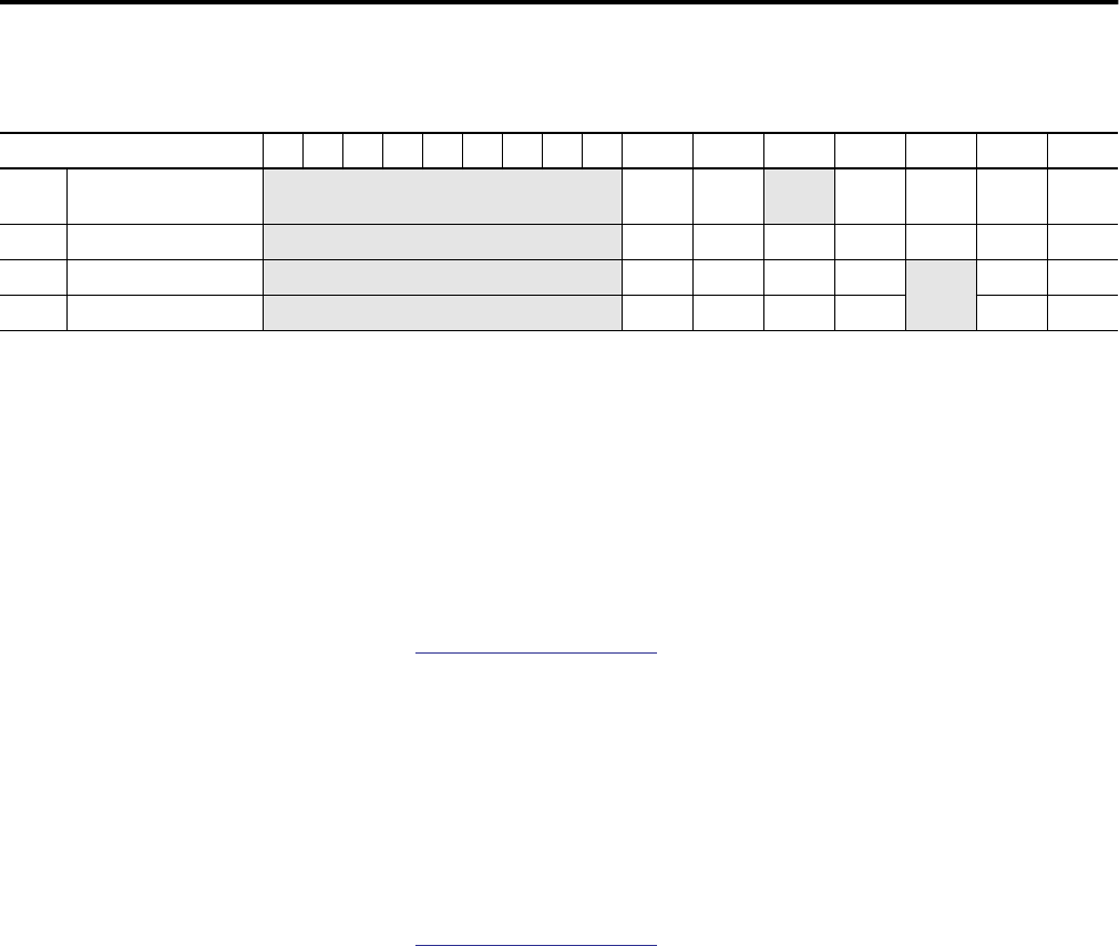
Input Array Words 15 14 13 12 11 10 09 08 07 06 05
(1)
04 03 02 01 00
12 Counter 0 Status Flags
Not used C0PW RV Not
used
IDW REZ CUdf COvf
22 Counter 1 Status Flags
Not used C1PW RV IC IDW REZ CUdf COvf
28 Counter 2 Status Flags
Not used C2PW RV IC IDW Not
used
CUdf COvf
34 Counter 3 Status Flags
Not used C3PW RV IC IDW CUdf COvf
(1) Bit 05 is not used for the packaged controller.