
Instruction Manual
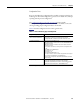
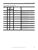
Table Of Contents
- 1769-UM006E-EN-P, Compact High-speed Counter Module User Manual
- Summary of Changes
- Table of Contents
- Preface
- 1 - Module Overview
- 2 - Module Operation
- 3 - Installation and Wiring
- 4 - Module Configuration, Output, and Input Data
- Configure the Module
- Configuration Array
- General Configuration Bits
- Filter Selection
- Program Mode and Program State Run
- Output Program Value (Out0ProgramValue through Out3ProgramValue)
- Output Fault Mode and Output Fault State Run
- Output Fault Value (Out0FaultValue through Out3FaultValue)
- Counter Maximum Count (CtrnMaxCount)
- Counter Minimum Count (CtrnMinCount)
- Counter Preset (CtrnPreset)
- Counter Hysteresis (CtrnHysteresis)
- Counter Scalar (CtrnScalar)
- Cyclic Rate Update Time (CtrnCyclicRateUpdateTime)
- Configuration Flags
- Range High Limit (Range0To11[n].HighLimit) and Range Low Limit (Range0To11[n].LowLimit)
- Range Output Control (Range0To11[n].OutputControl)
- Range Configuration Flags
- Output Array
- Output on Mask (OutputOnMask.0 through OutputOnMask.15)
- Output Off Mask (OutputOffMask.0 through OutputOffMask.15)
- Range Enable (RangeEn.0 through RangeEn.15)
- RBF - Reset Blown Fuse (ResetBlownFuse)
- Control Bits
- Range High Limit or Direct Write Value (Range12To15[n].HiLimOrDirWr)
- Range Low Limit (Range12To15[n].LowLimit)
- Range Output Control (Range12To15[n].OutputControl)
- Range Configuration Flags (12To15)
- Input Array
- Input State (InputStateA0 through InputStateZ1)
- Readback (Readback.0 through Readback.15)
- Status Flags
- Range Active (RangeActive.0 through RangeActive.15)
- Current Count (Ctr[n].CurrentCount)
- Stored Count (Ctr[n].StoredCount)
- Current Rate (Ctr[0].CurrentRate to Ctr[3].CurrentRate)
- Pulse Interval (Ctr[0].PulseInterval and Ctr[1].PulseInterval)
- Status Flags
- 5 - Diagnostics and Troubleshooting
- A - Specifications
- B - Program a 1769-HSC Module, CompactLogix Controller, and 845F Incremental Encoder with RSLogix 5000 Software
- C - Program a 1769-HSC Module, MicroLogix 1500 Controller, and 845F Incremental Encoder with RSLogix 500 Software
- D - Programming Quick Reference
- E - History of Changes
- Glossary
- Index
- Back Cover

Rockwell Automation Publication 1769-UM006E-EN-P - July 2013 113
Diagnostics and Troubleshooting Chapter 5
Configuration Diagnostics
When a configuration is sent, the module performs a diagnostic check to see that
the configuration is valid. This results in either a valid ModConfig bit or module
configuration error. See the
Configuration Error Codes table on page 117 for
configuration error codes.
Post Configuration Diagnostics
If the ModConfig bit in the input array is set, then the module has accepted the
configuration. Now, on every scan, each channel status flag in the input array is
examined. The output array is checked on each scan for compatibility with the
configuration array.
Non-critical versus
Critical Module Errors
The 1769-HSC module has non-critical and critical errors.
Non-critical Errors
Non-critical module errors are typically recoverable. Non-critical error
conditions are indicated by the extended error code. See the
Configuration Error
Codes table on page 117 for more information.
Critical Errors
Critical module errors are conditions that prevent normal or recoverable
operation of the system. When these types of errors occur, the system typically
leaves the Run or Program mode and enters the fault mode of operation until the
error can be dealt with. Critical module errors are indicated in the
General
Common Hardware Error Codes table on page 116.
TIP
The OK status indicator will be in a flashing red state for all of the error
codes in the Configuration Error Codes table on page 117.