
Instruction Manual
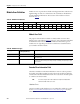
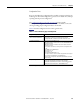
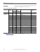
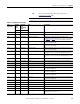
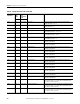
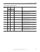
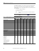
Table Of Contents
- 1769-UM006E-EN-P, Compact High-speed Counter Module User Manual
- Summary of Changes
- Table of Contents
- Preface
- 1 - Module Overview
- 2 - Module Operation
- 3 - Installation and Wiring
- 4 - Module Configuration, Output, and Input Data
- Configure the Module
- Configuration Array
- General Configuration Bits
- Filter Selection
- Program Mode and Program State Run
- Output Program Value (Out0ProgramValue through Out3ProgramValue)
- Output Fault Mode and Output Fault State Run
- Output Fault Value (Out0FaultValue through Out3FaultValue)
- Counter Maximum Count (CtrnMaxCount)
- Counter Minimum Count (CtrnMinCount)
- Counter Preset (CtrnPreset)
- Counter Hysteresis (CtrnHysteresis)
- Counter Scalar (CtrnScalar)
- Cyclic Rate Update Time (CtrnCyclicRateUpdateTime)
- Configuration Flags
- Range High Limit (Range0To11[n].HighLimit) and Range Low Limit (Range0To11[n].LowLimit)
- Range Output Control (Range0To11[n].OutputControl)
- Range Configuration Flags
- Output Array
- Output on Mask (OutputOnMask.0 through OutputOnMask.15)
- Output Off Mask (OutputOffMask.0 through OutputOffMask.15)
- Range Enable (RangeEn.0 through RangeEn.15)
- RBF - Reset Blown Fuse (ResetBlownFuse)
- Control Bits
- Range High Limit or Direct Write Value (Range12To15[n].HiLimOrDirWr)
- Range Low Limit (Range12To15[n].LowLimit)
- Range Output Control (Range12To15[n].OutputControl)
- Range Configuration Flags (12To15)
- Input Array
- Input State (InputStateA0 through InputStateZ1)
- Readback (Readback.0 through Readback.15)
- Status Flags
- Range Active (RangeActive.0 through RangeActive.15)
- Current Count (Ctr[n].CurrentCount)
- Stored Count (Ctr[n].StoredCount)
- Current Rate (Ctr[0].CurrentRate to Ctr[3].CurrentRate)
- Pulse Interval (Ctr[0].PulseInterval and Ctr[1].PulseInterval)
- Status Flags
- 5 - Diagnostics and Troubleshooting
- A - Specifications
- B - Program a 1769-HSC Module, CompactLogix Controller, and 845F Incremental Encoder with RSLogix 5000 Software
- C - Program a 1769-HSC Module, MicroLogix 1500 Controller, and 845F Incremental Encoder with RSLogix 500 Software
- D - Programming Quick Reference
- E - History of Changes
- Glossary
- Index
- Back Cover
114 Rockwell Automation Publication 1769-UM006E-EN-P - July 2013
Chapter 5 Diagnostics and Troubleshooting
Module Error Definition
Module errors are expressed in two fields as four-digit Hex format, with the most
significant digit as ‘don’t care’ and irrelevant. The two fields are ‘Module Error’
and ‘Extended Error Information’. The structure of the module error data is
shown in
Table 19.
Module Error Field
The purpose of the module error field is to classify module errors into three
distinct groups, as described in
Table 20. The type of error determines what kind
of information exists in the extended error information field. These types of
module errors are typically reported in the controller’s I/O status file. Refer to
your controller manual for details.
Extended Error Information Field
Check the extended error information field when a non-zero value is present in
the module error field. Depending upon the value in the module error field, the
extended error information field can contain error codes that are module-specific
or common to all 1769 modules.
Hardware Errors
General or module-specific hardware errors are indicated by module error code 1.
See the
General Common Hardware Error Codes table on page 116 for more
information.
Table 19 - Module Error Definition
‘Don’t Care’ Bits Module Error Extended Error Information
15 14 13 12 11 10 9 8 7 6 5 4 3 2 1 0
0000000000000000
Hex Digit 4 Hex Digit 3 Hex Digit 2 Hex Digit 1
Table 20 - Module Error Types
Error Type Module Error Field Value Bits
11 through 09 (Binary)
Description
No Errors 000 No error is present. The extended error field holds no additional information.
Hardware Errors 001 General and specific hardware error codes are specified in the extended error
information field.
Configuration Errors 010 Module-specific error codes are indicated in the extended error field. These error codes
correspond to options that you can change directly. For example, the input range or input
filter selection.
TIP
If no errors are present in the module error field, the extended error
information field will be set to zero.