
Instruction Manual
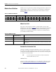
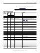
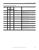
Table Of Contents
- 1769-UM006E-EN-P, Compact High-speed Counter Module User Manual
- Summary of Changes
- Table of Contents
- Preface
- 1 - Module Overview
- 2 - Module Operation
- 3 - Installation and Wiring
- 4 - Module Configuration, Output, and Input Data
- Configure the Module
- Configuration Array
- General Configuration Bits
- Filter Selection
- Program Mode and Program State Run
- Output Program Value (Out0ProgramValue through Out3ProgramValue)
- Output Fault Mode and Output Fault State Run
- Output Fault Value (Out0FaultValue through Out3FaultValue)
- Counter Maximum Count (CtrnMaxCount)
- Counter Minimum Count (CtrnMinCount)
- Counter Preset (CtrnPreset)
- Counter Hysteresis (CtrnHysteresis)
- Counter Scalar (CtrnScalar)
- Cyclic Rate Update Time (CtrnCyclicRateUpdateTime)
- Configuration Flags
- Range High Limit (Range0To11[n].HighLimit) and Range Low Limit (Range0To11[n].LowLimit)
- Range Output Control (Range0To11[n].OutputControl)
- Range Configuration Flags
- Output Array
- Output on Mask (OutputOnMask.0 through OutputOnMask.15)
- Output Off Mask (OutputOffMask.0 through OutputOffMask.15)
- Range Enable (RangeEn.0 through RangeEn.15)
- RBF - Reset Blown Fuse (ResetBlownFuse)
- Control Bits
- Range High Limit or Direct Write Value (Range12To15[n].HiLimOrDirWr)
- Range Low Limit (Range12To15[n].LowLimit)
- Range Output Control (Range12To15[n].OutputControl)
- Range Configuration Flags (12To15)
- Input Array
- Input State (InputStateA0 through InputStateZ1)
- Readback (Readback.0 through Readback.15)
- Status Flags
- Range Active (RangeActive.0 through RangeActive.15)
- Current Count (Ctr[n].CurrentCount)
- Stored Count (Ctr[n].StoredCount)
- Current Rate (Ctr[0].CurrentRate to Ctr[3].CurrentRate)
- Pulse Interval (Ctr[0].PulseInterval and Ctr[1].PulseInterval)
- Status Flags
- 5 - Diagnostics and Troubleshooting
- A - Specifications
- B - Program a 1769-HSC Module, CompactLogix Controller, and 845F Incremental Encoder with RSLogix 5000 Software
- C - Program a 1769-HSC Module, MicroLogix 1500 Controller, and 845F Incremental Encoder with RSLogix 500 Software
- D - Programming Quick Reference
- E - History of Changes
- Glossary
- Index
- Back Cover
116 Rockwell Automation Publication 1769-UM006E-EN-P - July 2013
Chapter 5 Diagnostics and Troubleshooting
Error Codes
The tables in this section explain the extended error codes for general common
hardware errors, configuration errors, and runtime errors.
Table 22 - General Common Hardware Error Codes
Error Type Hex
Equivalent
(1)
Module
Error Code
Extended Error
Information
Code
Description Status of the
OK Indicator
(2)
Binary Binary
No Error X000 000 0 0000 0000 OK, normal operating condition. Solid or flashing green
General Common
Hardware Error
X200 001 0 0000 0000 General hardware error; no additional
information
Solid red
X201 001 0 0000 0001 Power-up reset state Briefly red
X202 001 0 0000 0010 Bus master incompatibility Solid red
X203 001 0 0000 0011 General hardware error Solid red
X210 001 0 0000 1010 General microprocessor error Solid red
X211 001 0 0000 1011 Microprocessor internal register error Solid red
X212 001 0 0000 1100 Microprocessor special function register error Solid red
X213 001 0 0000 1101 Microprocessor internal memory error Solid red
X214 001 0 0000 1110 Microprocessor timer error Solid red
X215 001 0 0000 1111 Microprocessor interrupt error Solid red
X216 001 0 0001 0000 Microprocessor watchdog error Solid red
X220 001 0 0001 1000 Firmware corrupt Solid red
X221 001 0 0001 1001 Firmware checksum error in non-volatile RAM Solid red
X222 001 0 0001 1010 Firmware checksum error in RAM Solid red
X230 001 0 0001 1110 External RAM test error Solid red
X231 001 0 0001 1111 External RAM cell test error Solid red
X240 001 0 0010 0100 Gate array loading failed Solid red
X250 001 0 0011 0010 External watchdog error Solid red
(1) X represents the ‘Don’t Care’ digit.
(2) See the Diagnostic Indicators table on page 112 for recommendation based on status indicator operation.