
Instruction Manual

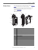
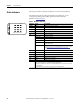
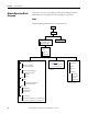
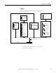
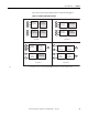
Table Of Contents
- 1769-UM006E-EN-P, Compact High-speed Counter Module User Manual
- Summary of Changes
- Table of Contents
- Preface
- 1 - Module Overview
- 2 - Module Operation
- 3 - Installation and Wiring
- 4 - Module Configuration, Output, and Input Data
- Configure the Module
- Configuration Array
- General Configuration Bits
- Filter Selection
- Program Mode and Program State Run
- Output Program Value (Out0ProgramValue through Out3ProgramValue)
- Output Fault Mode and Output Fault State Run
- Output Fault Value (Out0FaultValue through Out3FaultValue)
- Counter Maximum Count (CtrnMaxCount)
- Counter Minimum Count (CtrnMinCount)
- Counter Preset (CtrnPreset)
- Counter Hysteresis (CtrnHysteresis)
- Counter Scalar (CtrnScalar)
- Cyclic Rate Update Time (CtrnCyclicRateUpdateTime)
- Configuration Flags
- Range High Limit (Range0To11[n].HighLimit) and Range Low Limit (Range0To11[n].LowLimit)
- Range Output Control (Range0To11[n].OutputControl)
- Range Configuration Flags
- Output Array
- Output on Mask (OutputOnMask.0 through OutputOnMask.15)
- Output Off Mask (OutputOffMask.0 through OutputOffMask.15)
- Range Enable (RangeEn.0 through RangeEn.15)
- RBF - Reset Blown Fuse (ResetBlownFuse)
- Control Bits
- Range High Limit or Direct Write Value (Range12To15[n].HiLimOrDirWr)
- Range Low Limit (Range12To15[n].LowLimit)
- Range Output Control (Range12To15[n].OutputControl)
- Range Configuration Flags (12To15)
- Input Array
- Input State (InputStateA0 through InputStateZ1)
- Readback (Readback.0 through Readback.15)
- Status Flags
- Range Active (RangeActive.0 through RangeActive.15)
- Current Count (Ctr[n].CurrentCount)
- Stored Count (Ctr[n].StoredCount)
- Current Rate (Ctr[0].CurrentRate to Ctr[3].CurrentRate)
- Pulse Interval (Ctr[0].PulseInterval and Ctr[1].PulseInterval)
- Status Flags
- 5 - Diagnostics and Troubleshooting
- A - Specifications
- B - Program a 1769-HSC Module, CompactLogix Controller, and 845F Incremental Encoder with RSLogix 5000 Software
- C - Program a 1769-HSC Module, MicroLogix 1500 Controller, and 845F Incremental Encoder with RSLogix 500 Software
- D - Programming Quick Reference
- E - History of Changes
- Glossary
- Index
- Back Cover

12 Rockwell Automation Publication 1769-UM006E-EN-P - July 2013
Chapter 1 Module Overview
Counters
The module is capable of counting pulses in either direction (forward, reverse, up,
down). A maximum of four pulse counters (or two quadrature counters) are
available. Each 32-bit counter can count to ±2 billion as a ring or linear counter.
In addition to providing a count value, the module provides a rate value up to
±1 MHz, dependent upon the type of input (the L23 packaged controller’s HSC
module functionality does not provide rate values). The rate value (as modified
by scalar) is the input frequency to the counter. When the count value is
increasing, the rate value is positive. When the count value is decreasing, the rate
value is negative.
Counters can also be reset or preset to any value between user-defined minimum
and maximum values. Preset can be accomplished from the user program or at a
Z-input event. The Z-input can also generate a capture value and/or freeze (gate)
the counters.
Inputs
The module features six, high-speed differential inputs labeled ±A0, ±B0, ±Z0,
±A1, ±B1, and ±Z1. These inputs support two quadrature encoders with ABZ
inputs and/or up to four discrete count inputs. In addition, x1, x2, and x4
encoder configurations are provided to fully use the capabilities of high
resolution quadrature encoders. The inputs can be wired for standard differential
line driver output devices, as well as single-ended devices such as limit switches,
photo eyes, and proximity sensors. Inputs are optically isolated from the bus and
from one another, and have an operational range of 2.6…30V DC.
Outputs
Sixteen outputs are available: four on-board (real) and twelve virtual bits. All
16 outputs can be individually controlled by the module or by the user control
program.
The four on-board (real) outputs are DC sourcing, powered by a user-supplied
(5…30V DC) power source. These outputs are electronically protected from
current overloads and short-circuit conditions. Overcurrent status is monitored
and fed back to the user program. Output states are determined by a combination
of output data, configuration data, ranges, and overcurrent status.
See
Output Control Example on page 44 for a description of how the module
determines output status.