
Instruction Manual

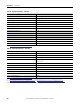
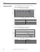
Table Of Contents
- 1769-UM006E-EN-P, Compact High-speed Counter Module User Manual
- Summary of Changes
- Table of Contents
- Preface
- 1 - Module Overview
- 2 - Module Operation
- 3 - Installation and Wiring
- 4 - Module Configuration, Output, and Input Data
- Configure the Module
- Configuration Array
- General Configuration Bits
- Filter Selection
- Program Mode and Program State Run
- Output Program Value (Out0ProgramValue through Out3ProgramValue)
- Output Fault Mode and Output Fault State Run
- Output Fault Value (Out0FaultValue through Out3FaultValue)
- Counter Maximum Count (CtrnMaxCount)
- Counter Minimum Count (CtrnMinCount)
- Counter Preset (CtrnPreset)
- Counter Hysteresis (CtrnHysteresis)
- Counter Scalar (CtrnScalar)
- Cyclic Rate Update Time (CtrnCyclicRateUpdateTime)
- Configuration Flags
- Range High Limit (Range0To11[n].HighLimit) and Range Low Limit (Range0To11[n].LowLimit)
- Range Output Control (Range0To11[n].OutputControl)
- Range Configuration Flags
- Output Array
- Output on Mask (OutputOnMask.0 through OutputOnMask.15)
- Output Off Mask (OutputOffMask.0 through OutputOffMask.15)
- Range Enable (RangeEn.0 through RangeEn.15)
- RBF - Reset Blown Fuse (ResetBlownFuse)
- Control Bits
- Range High Limit or Direct Write Value (Range12To15[n].HiLimOrDirWr)
- Range Low Limit (Range12To15[n].LowLimit)
- Range Output Control (Range12To15[n].OutputControl)
- Range Configuration Flags (12To15)
- Input Array
- Input State (InputStateA0 through InputStateZ1)
- Readback (Readback.0 through Readback.15)
- Status Flags
- Range Active (RangeActive.0 through RangeActive.15)
- Current Count (Ctr[n].CurrentCount)
- Stored Count (Ctr[n].StoredCount)
- Current Rate (Ctr[0].CurrentRate to Ctr[3].CurrentRate)
- Pulse Interval (Ctr[0].PulseInterval and Ctr[1].PulseInterval)
- Status Flags
- 5 - Diagnostics and Troubleshooting
- A - Specifications
- B - Program a 1769-HSC Module, CompactLogix Controller, and 845F Incremental Encoder with RSLogix 5000 Software
- C - Program a 1769-HSC Module, MicroLogix 1500 Controller, and 845F Incremental Encoder with RSLogix 500 Software
- D - Programming Quick Reference
- E - History of Changes
- Glossary
- Index
- Back Cover
Rockwell Automation Publication 1769-UM006E-EN-P - July 2013 123
Appendix A
Specifications
IMPORTANT
For specifications for the packaged controllers, refer to the CompactLogix
Packaged Controller Installation Instructions, publication 1769-IN082.
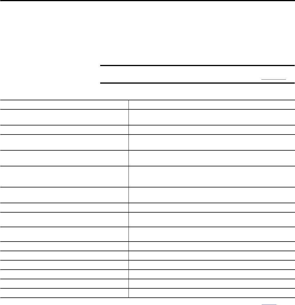
Table 25 - Technical Specifications - 1769-HSC
Attribute 1769-HSC
Dimensions (HxWxD),approx. 118 x 35 x 87 mm (4.65 x 1.38 x 3.43 in.)
Height including mounting tabs is 138 mm (5.43 in.)
Shipping weight (with carton), . 309 g (0.681 lb)
Bus current draw, max 425 mA at 5V DC
0mAat24VDC
Heat dissipation 6.21 W
The Watts per point, plus the minimum Watts, with all points energized
Isolation voltage 75V (continuous), reinforced Insulation type, channel-to-system
and channel-to-channel
Type tested at 1200V AC for 2 s
All supply power and/or current ratings Input: 30V DC 40 °C (104 °F )
Output: 1 A per channel, 4 A per module, 30V DC 40 °C (104 °F )
Power supply distance rating Module cannot be more than four modules away from a system power supply
Recommended cable Individually shielded, twisted-pair cable (for the type recommended by the encoder or
sensor manufacturer)
Wire size 0.32…2.1 mm
2
(22…14 AWG) solid copper wire or 0.32…1.3 mm
2
(22…16 AWG)
stranded copper wire rated at 90 °C (194 °F ) insulation max
Wiring category 2 - on signal ports
(1)
Vendor ID code 1
Product type code 109
Product code 19
Enclosure type rating None (open-style)
North American temp code T3C
(1) Use this Conductor Category information for planning conductor routing. Refer to Industrial Automation Wiring and Grounding Guidelines, publication 1770-4.1.