
Instruction Manual

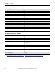
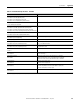
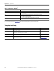
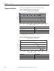
Table Of Contents
- 1769-UM006E-EN-P, Compact High-speed Counter Module User Manual
- Summary of Changes
- Table of Contents
- Preface
- 1 - Module Overview
- 2 - Module Operation
- 3 - Installation and Wiring
- 4 - Module Configuration, Output, and Input Data
- Configure the Module
- Configuration Array
- General Configuration Bits
- Filter Selection
- Program Mode and Program State Run
- Output Program Value (Out0ProgramValue through Out3ProgramValue)
- Output Fault Mode and Output Fault State Run
- Output Fault Value (Out0FaultValue through Out3FaultValue)
- Counter Maximum Count (CtrnMaxCount)
- Counter Minimum Count (CtrnMinCount)
- Counter Preset (CtrnPreset)
- Counter Hysteresis (CtrnHysteresis)
- Counter Scalar (CtrnScalar)
- Cyclic Rate Update Time (CtrnCyclicRateUpdateTime)
- Configuration Flags
- Range High Limit (Range0To11[n].HighLimit) and Range Low Limit (Range0To11[n].LowLimit)
- Range Output Control (Range0To11[n].OutputControl)
- Range Configuration Flags
- Output Array
- Output on Mask (OutputOnMask.0 through OutputOnMask.15)
- Output Off Mask (OutputOffMask.0 through OutputOffMask.15)
- Range Enable (RangeEn.0 through RangeEn.15)
- RBF - Reset Blown Fuse (ResetBlownFuse)
- Control Bits
- Range High Limit or Direct Write Value (Range12To15[n].HiLimOrDirWr)
- Range Low Limit (Range12To15[n].LowLimit)
- Range Output Control (Range12To15[n].OutputControl)
- Range Configuration Flags (12To15)
- Input Array
- Input State (InputStateA0 through InputStateZ1)
- Readback (Readback.0 through Readback.15)
- Status Flags
- Range Active (RangeActive.0 through RangeActive.15)
- Current Count (Ctr[n].CurrentCount)
- Stored Count (Ctr[n].StoredCount)
- Current Rate (Ctr[0].CurrentRate to Ctr[3].CurrentRate)
- Pulse Interval (Ctr[0].PulseInterval and Ctr[1].PulseInterval)
- Status Flags
- 5 - Diagnostics and Troubleshooting
- A - Specifications
- B - Program a 1769-HSC Module, CompactLogix Controller, and 845F Incremental Encoder with RSLogix 5000 Software
- C - Program a 1769-HSC Module, MicroLogix 1500 Controller, and 845F Incremental Encoder with RSLogix 500 Software
- D - Programming Quick Reference
- E - History of Changes
- Glossary
- Index
- Back Cover

124 Rockwell Automation Publication 1769-UM006E-EN-P - July 2013
Appendix A Specifications
Table 26 - Input Specifications - 1769-HSC
Attribute 1769-HSC
No. of inputs 2 quadrature (ABZ) differential inputs
Input voltage range 2.6…30V DC
(1)
On-state voltage, max 30V DC
(1)
On-state voltage, min 2.6 V DC
On-state current, min 6.8 mA
Off-state voltage, max 1.0V DC
Off-state current, max 1.5 mA
Off-state leakage current, max 1.5 mA
Input current, max 15 mA
Input current, min 6.8 mA
Input impedance, nom 1950
Pulse width, min 250 nsec
Pulse separation, min 131 nsec
Input frequency, max 1 MHz
(1) See Maximum Input Voltage - 24V DC Operation on page 128
Table 27 - Output Specifications - 1769-HSC
Attribute 1769-HSC
No. of outputs 16 total, 4 physical and 12 virtual
Output voltage range 5…30V DC
(1)
On-state voltage, max User power - 0.1V DC
On-state current, max 1 A per point
(2)
4 A per module
(3)
On-state current, min 1 mA
On-state voltage drop, max 0.5V DC
Off-state leakage current, max
5
µA
Input current, min 6.8 mA
Turn-on time, max 400 µs
(4)
Turn-off time, max 200 µs
Reverse polarity protection 30V DC
(1) See Maximum Output Voltage - 24V DC Operation on page 128.
(2) See Maximum Output Current per Point - 5V DC Operation on page 129 and Maximum Output Current per Point - 24V DC Operation on page 130.
(3) See Maximum Output Current per Module - 5V DC Operation on page 129 and Maximum Output Current per Module - 24V DC Operation on page 130.
(4) Maximum turn-on time applies to output voltage range of 5…7V DC. For output voltages greater than 7V DC, the maximum turn-on time is 200 µs.