
Instruction Manual

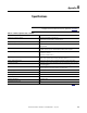
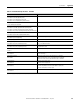
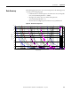
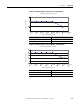
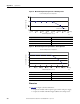
Table Of Contents
- 1769-UM006E-EN-P, Compact High-speed Counter Module User Manual
- Summary of Changes
- Table of Contents
- Preface
- 1 - Module Overview
- 2 - Module Operation
- 3 - Installation and Wiring
- 4 - Module Configuration, Output, and Input Data
- Configure the Module
- Configuration Array
- General Configuration Bits
- Filter Selection
- Program Mode and Program State Run
- Output Program Value (Out0ProgramValue through Out3ProgramValue)
- Output Fault Mode and Output Fault State Run
- Output Fault Value (Out0FaultValue through Out3FaultValue)
- Counter Maximum Count (CtrnMaxCount)
- Counter Minimum Count (CtrnMinCount)
- Counter Preset (CtrnPreset)
- Counter Hysteresis (CtrnHysteresis)
- Counter Scalar (CtrnScalar)
- Cyclic Rate Update Time (CtrnCyclicRateUpdateTime)
- Configuration Flags
- Range High Limit (Range0To11[n].HighLimit) and Range Low Limit (Range0To11[n].LowLimit)
- Range Output Control (Range0To11[n].OutputControl)
- Range Configuration Flags
- Output Array
- Output on Mask (OutputOnMask.0 through OutputOnMask.15)
- Output Off Mask (OutputOffMask.0 through OutputOffMask.15)
- Range Enable (RangeEn.0 through RangeEn.15)
- RBF - Reset Blown Fuse (ResetBlownFuse)
- Control Bits
- Range High Limit or Direct Write Value (Range12To15[n].HiLimOrDirWr)
- Range Low Limit (Range12To15[n].LowLimit)
- Range Output Control (Range12To15[n].OutputControl)
- Range Configuration Flags (12To15)
- Input Array
- Input State (InputStateA0 through InputStateZ1)
- Readback (Readback.0 through Readback.15)
- Status Flags
- Range Active (RangeActive.0 through RangeActive.15)
- Current Count (Ctr[n].CurrentCount)
- Stored Count (Ctr[n].StoredCount)
- Current Rate (Ctr[0].CurrentRate to Ctr[3].CurrentRate)
- Pulse Interval (Ctr[0].PulseInterval and Ctr[1].PulseInterval)
- Status Flags
- 5 - Diagnostics and Troubleshooting
- A - Specifications
- B - Program a 1769-HSC Module, CompactLogix Controller, and 845F Incremental Encoder with RSLogix 5000 Software
- C - Program a 1769-HSC Module, MicroLogix 1500 Controller, and 845F Incremental Encoder with RSLogix 500 Software
- D - Programming Quick Reference
- E - History of Changes
- Glossary
- Index
- Back Cover
128 Rockwell Automation Publication 1769-UM006E-EN-P - July 2013
Appendix A Specifications
Temperature Derating
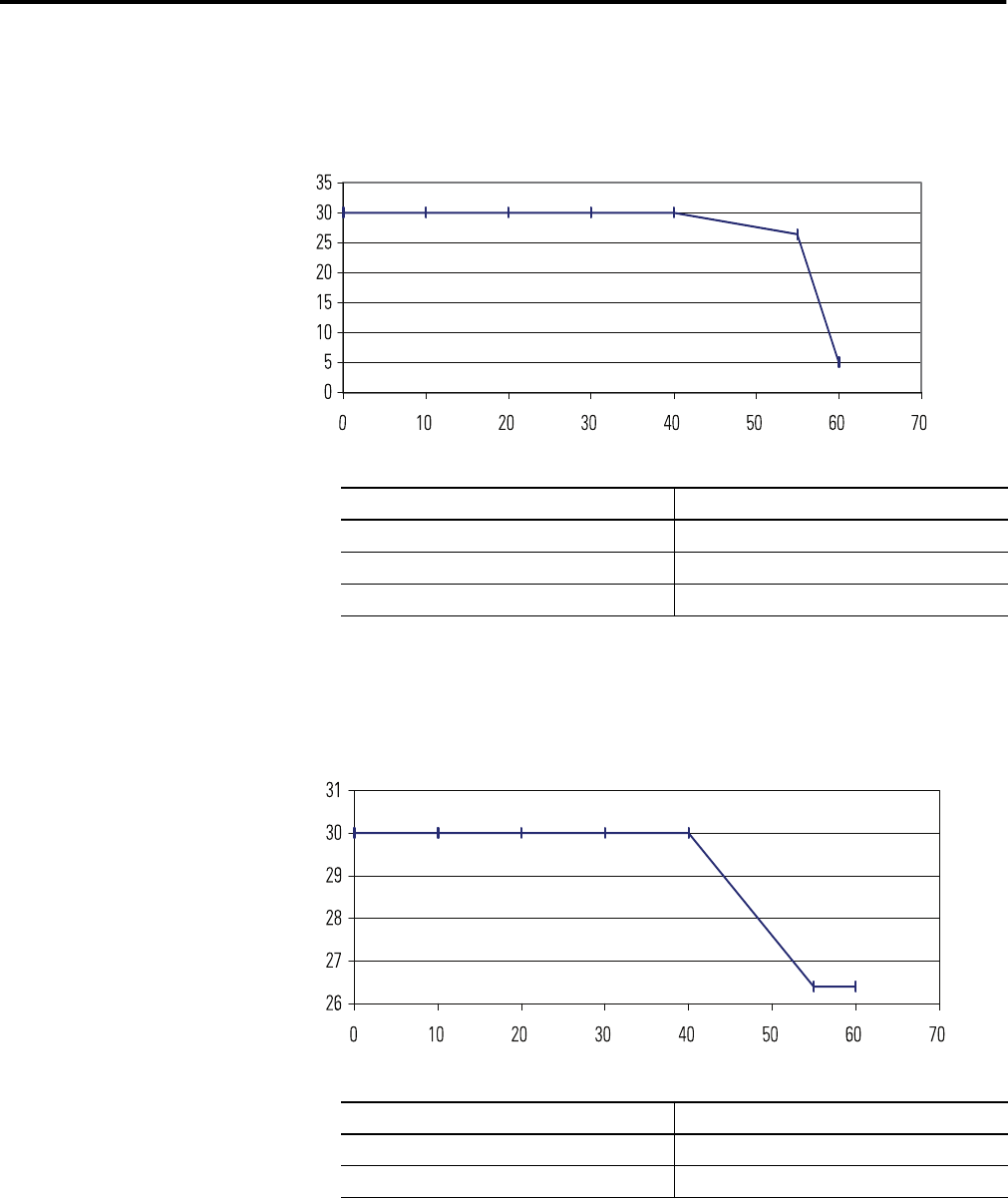
Refer to the following figures for 1769-HSC temperature derating.
Figure 22 - Maximum Input Voltage - 24V DC Operation
Figure 23 - Maximum Output Voltage - 24V DC Operation
(-32) (50) (68) (86) (104) (122) (140) (158)
Voltage Derating Based on Temperature
Ambient Temperature, °C (°F))
Volts (DC)
26.4V DC at
55 °C (131 °F)
45204
Temperature Derated Voltage
(1)
(1) Input voltage derating between 55…60 °C is achieved by using a dropping resistor.
For 24V DC input voltage, use a 2.4 k, ½ W resistor.
For input voltages greater than 24V DC, usea½Wresistor with value: 125 x (V
in
- 5V).
0…40 °C (-32…104 °F) 30V DC
55 °C (131 °F) 26.4V DC
60 °C (140 °F) 5V DC
(-32)
(50) (68) (86) (104) (122)
(140)
(158)
Voltage Derating Based on Temperature
Ambient Temperature, °C (°F)
Volts (DC)
26.4V DC at
55 °C (131 °F)
45205
Temperature Derated Voltage
0…40 °C (-32…104 °F) 30V DC
55…60 °C (131…140 °F) 26.4V DC