
Instruction Manual

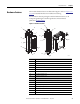
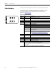
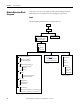
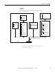
Table Of Contents
- 1769-UM006E-EN-P, Compact High-speed Counter Module User Manual
- Summary of Changes
- Table of Contents
- Preface
- 1 - Module Overview
- 2 - Module Operation
- 3 - Installation and Wiring
- 4 - Module Configuration, Output, and Input Data
- Configure the Module
- Configuration Array
- General Configuration Bits
- Filter Selection
- Program Mode and Program State Run
- Output Program Value (Out0ProgramValue through Out3ProgramValue)
- Output Fault Mode and Output Fault State Run
- Output Fault Value (Out0FaultValue through Out3FaultValue)
- Counter Maximum Count (CtrnMaxCount)
- Counter Minimum Count (CtrnMinCount)
- Counter Preset (CtrnPreset)
- Counter Hysteresis (CtrnHysteresis)
- Counter Scalar (CtrnScalar)
- Cyclic Rate Update Time (CtrnCyclicRateUpdateTime)
- Configuration Flags
- Range High Limit (Range0To11[n].HighLimit) and Range Low Limit (Range0To11[n].LowLimit)
- Range Output Control (Range0To11[n].OutputControl)
- Range Configuration Flags
- Output Array
- Output on Mask (OutputOnMask.0 through OutputOnMask.15)
- Output Off Mask (OutputOffMask.0 through OutputOffMask.15)
- Range Enable (RangeEn.0 through RangeEn.15)
- RBF - Reset Blown Fuse (ResetBlownFuse)
- Control Bits
- Range High Limit or Direct Write Value (Range12To15[n].HiLimOrDirWr)
- Range Low Limit (Range12To15[n].LowLimit)
- Range Output Control (Range12To15[n].OutputControl)
- Range Configuration Flags (12To15)
- Input Array
- Input State (InputStateA0 through InputStateZ1)
- Readback (Readback.0 through Readback.15)
- Status Flags
- Range Active (RangeActive.0 through RangeActive.15)
- Current Count (Ctr[n].CurrentCount)
- Stored Count (Ctr[n].StoredCount)
- Current Rate (Ctr[0].CurrentRate to Ctr[3].CurrentRate)
- Pulse Interval (Ctr[0].PulseInterval and Ctr[1].PulseInterval)
- Status Flags
- 5 - Diagnostics and Troubleshooting
- A - Specifications
- B - Program a 1769-HSC Module, CompactLogix Controller, and 845F Incremental Encoder with RSLogix 5000 Software
- C - Program a 1769-HSC Module, MicroLogix 1500 Controller, and 845F Incremental Encoder with RSLogix 500 Software
- D - Programming Quick Reference
- E - History of Changes
- Glossary
- Index
- Back Cover
Rockwell Automation Publication 1769-UM006E-EN-P - July 2013 13
Module Overview Chapter 1
Hardware Features
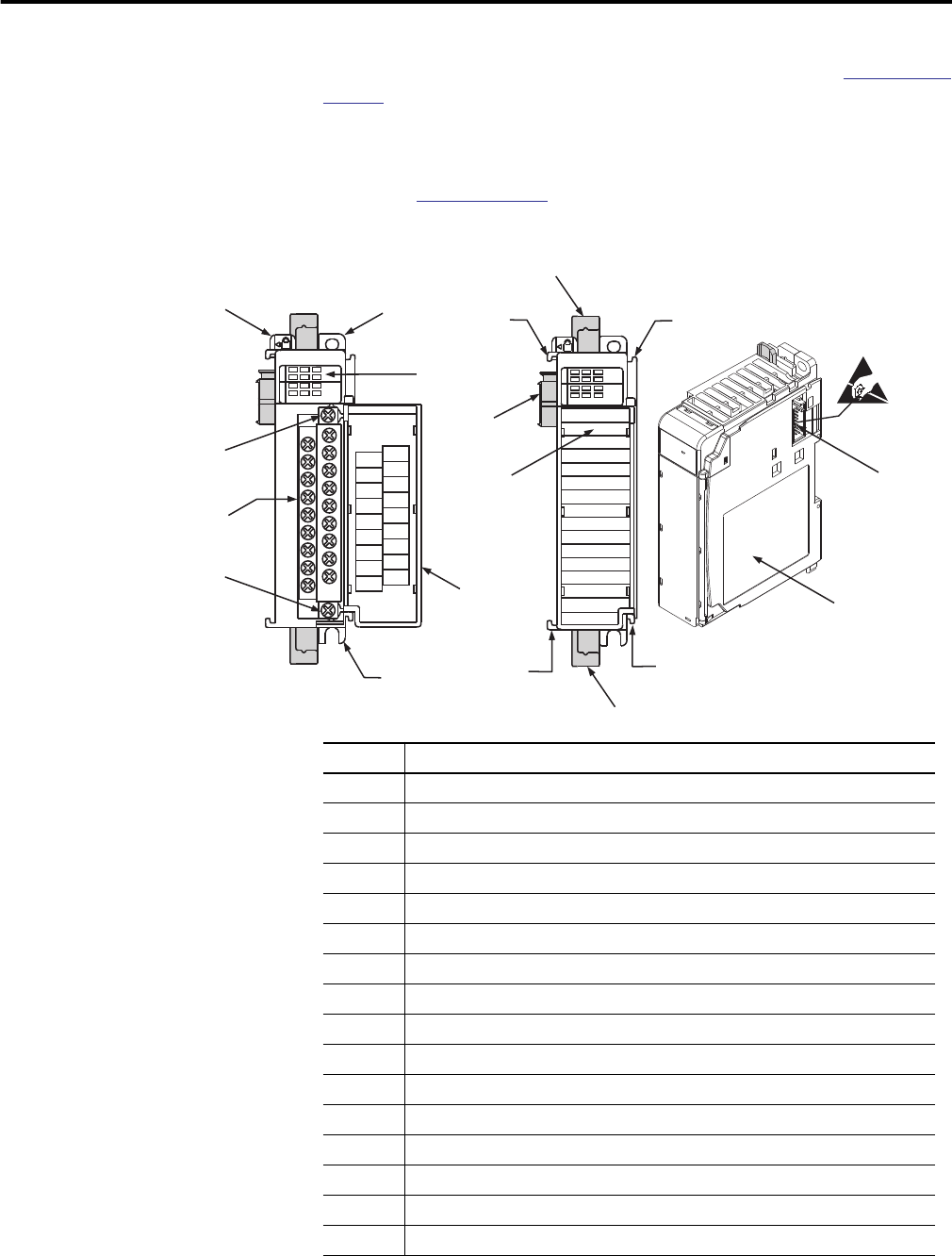
The module’s hardware features are illustrated in Figure 1. Refer to Chapter 3 on
page 45 for detailed information on installation and wiring.
For information about the packaged controllers’ hardware features, see the
CompactLogix Packaged Controllers Quick Start and User Manual,
publication
IASIMP-QS010.
Figure 1 - Hardware Features
1769-HSC
DANGER
Do Not Remove RTB Under Power
Unless Area is Non-Hazardous
Ensure Adjacent
Bus Lever is Unlatched/Latched
Before/After
Removing/Inserting Module
OUT 2
A1-
Z1-
OUT DC
COM
B0-
Z0-
B1-
OUT 0
OUT DC
+5V/24V
A0+
Z0+
B1+
OUT 3
OUT 1
B0+
A1+
Z1+
A0-
High Speed Counter
02
13
A0 B0
A1 B1
Z0
Z1
IN OUT
High Speed Counter
02
13
A0 B0
A1 B1
Z0
Z1
IN OUT
1
2a
3
4
2b
5b
5
5a
9a
8a
6b
7
8b
9b
8b
10
6a
8a
45271
Item Description
1 Bus lever
2a Upper panel mounting tab
2b Lower panel mounting tab
3 Module status indicators (6 Input, 4 Output, 1 Fuse, 1 OK)
4 Module door with terminal identification label
5 Removable terminal block (RTB) with finger-safe cover
5a RTB upper-retaining screw
5b RTB lower-retaining screw
6a Movable bus connector (bus interface) with female pins
6b Stationary bus connector (bus interface) with male pins
7 Nameplate label
8a Upper tongue-and-groove slots
8b Lower tongue-and-groove slots
9a Upper DIN-rail latch
9b Lower DIN-rail latch
10 Write-on label for user identification tags