
Instruction Manual

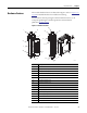
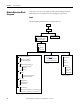
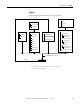
Table Of Contents
- 1769-UM006E-EN-P, Compact High-speed Counter Module User Manual
- Summary of Changes
- Table of Contents
- Preface
- 1 - Module Overview
- 2 - Module Operation
- 3 - Installation and Wiring
- 4 - Module Configuration, Output, and Input Data
- Configure the Module
- Configuration Array
- General Configuration Bits
- Filter Selection
- Program Mode and Program State Run
- Output Program Value (Out0ProgramValue through Out3ProgramValue)
- Output Fault Mode and Output Fault State Run
- Output Fault Value (Out0FaultValue through Out3FaultValue)
- Counter Maximum Count (CtrnMaxCount)
- Counter Minimum Count (CtrnMinCount)
- Counter Preset (CtrnPreset)
- Counter Hysteresis (CtrnHysteresis)
- Counter Scalar (CtrnScalar)
- Cyclic Rate Update Time (CtrnCyclicRateUpdateTime)
- Configuration Flags
- Range High Limit (Range0To11[n].HighLimit) and Range Low Limit (Range0To11[n].LowLimit)
- Range Output Control (Range0To11[n].OutputControl)
- Range Configuration Flags
- Output Array
- Output on Mask (OutputOnMask.0 through OutputOnMask.15)
- Output Off Mask (OutputOffMask.0 through OutputOffMask.15)
- Range Enable (RangeEn.0 through RangeEn.15)
- RBF - Reset Blown Fuse (ResetBlownFuse)
- Control Bits
- Range High Limit or Direct Write Value (Range12To15[n].HiLimOrDirWr)
- Range Low Limit (Range12To15[n].LowLimit)
- Range Output Control (Range12To15[n].OutputControl)
- Range Configuration Flags (12To15)
- Input Array
- Input State (InputStateA0 through InputStateZ1)
- Readback (Readback.0 through Readback.15)
- Status Flags
- Range Active (RangeActive.0 through RangeActive.15)
- Current Count (Ctr[n].CurrentCount)
- Stored Count (Ctr[n].StoredCount)
- Current Rate (Ctr[0].CurrentRate to Ctr[3].CurrentRate)
- Pulse Interval (Ctr[0].PulseInterval and Ctr[1].PulseInterval)
- Status Flags
- 5 - Diagnostics and Troubleshooting
- A - Specifications
- B - Program a 1769-HSC Module, CompactLogix Controller, and 845F Incremental Encoder with RSLogix 5000 Software
- C - Program a 1769-HSC Module, MicroLogix 1500 Controller, and 845F Incremental Encoder with RSLogix 500 Software
- D - Programming Quick Reference
- E - History of Changes
- Glossary
- Index
- Back Cover
16 Rockwell Automation Publication 1769-UM006E-EN-P - July 2013
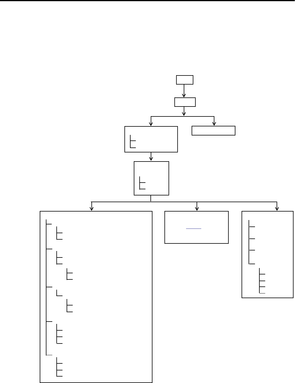
Chapter 2 Module Operation
Module Operation Block
Diagrams
To provide an overview of the module operation, the block diagrams indicate
relationships between module functions and configuration parameters.
Inputs
The following diagram illustrates how the inputs function.
Count
Min/Max and Linear/Ring
Overflow (ResetOvf)
(1)
Underflow (ResetUdf)
(1)
Pulse Interval
(2)
See page 32 to
determine how and when
to use to calculate rates.
Store
CtrnConfig.StorageMode_0
RisingEdgeZ (reset REZ)
(1)
ZInhibit
ZInvert
Enable
CtrnEn
CtrnConfig.StorageMode_1
InputStateZn ‘gating’
Direct Write
HiLimOrDirWr
LoadDirectWrite
ToThisCounter
Preset
CtrnSoftPreset
CtrnConfig.StorageMode_2 and Rising Edge Z
Automatic PresetWarning (Preset Warning)
(1)
Rate
(3)
Update Time
Scalar
Hysteresis
Rate Valid
Input
NumberOfCounters
Operational Mode
Decoded
Discrete Input State
Filtering
Pulse
Direction
DirInvert
DirInhibit
Overflow
Underflow
Preset
Direct Write
(1) Resets.
(2) Does not apply to packaged
controller.
(3) Does not apply to
packaged controller.