
Instruction Manual

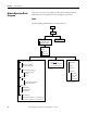
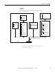
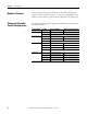
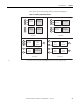
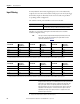
Table Of Contents
- 1769-UM006E-EN-P, Compact High-speed Counter Module User Manual
- Summary of Changes
- Table of Contents
- Preface
- 1 - Module Overview
- 2 - Module Operation
- 3 - Installation and Wiring
- 4 - Module Configuration, Output, and Input Data
- Configure the Module
- Configuration Array
- General Configuration Bits
- Filter Selection
- Program Mode and Program State Run
- Output Program Value (Out0ProgramValue through Out3ProgramValue)
- Output Fault Mode and Output Fault State Run
- Output Fault Value (Out0FaultValue through Out3FaultValue)
- Counter Maximum Count (CtrnMaxCount)
- Counter Minimum Count (CtrnMinCount)
- Counter Preset (CtrnPreset)
- Counter Hysteresis (CtrnHysteresis)
- Counter Scalar (CtrnScalar)
- Cyclic Rate Update Time (CtrnCyclicRateUpdateTime)
- Configuration Flags
- Range High Limit (Range0To11[n].HighLimit) and Range Low Limit (Range0To11[n].LowLimit)
- Range Output Control (Range0To11[n].OutputControl)
- Range Configuration Flags
- Output Array
- Output on Mask (OutputOnMask.0 through OutputOnMask.15)
- Output Off Mask (OutputOffMask.0 through OutputOffMask.15)
- Range Enable (RangeEn.0 through RangeEn.15)
- RBF - Reset Blown Fuse (ResetBlownFuse)
- Control Bits
- Range High Limit or Direct Write Value (Range12To15[n].HiLimOrDirWr)
- Range Low Limit (Range12To15[n].LowLimit)
- Range Output Control (Range12To15[n].OutputControl)
- Range Configuration Flags (12To15)
- Input Array
- Input State (InputStateA0 through InputStateZ1)
- Readback (Readback.0 through Readback.15)
- Status Flags
- Range Active (RangeActive.0 through RangeActive.15)
- Current Count (Ctr[n].CurrentCount)
- Stored Count (Ctr[n].StoredCount)
- Current Rate (Ctr[0].CurrentRate to Ctr[3].CurrentRate)
- Pulse Interval (Ctr[0].PulseInterval and Ctr[1].PulseInterval)
- Status Flags
- 5 - Diagnostics and Troubleshooting
- A - Specifications
- B - Program a 1769-HSC Module, CompactLogix Controller, and 845F Incremental Encoder with RSLogix 5000 Software
- C - Program a 1769-HSC Module, MicroLogix 1500 Controller, and 845F Incremental Encoder with RSLogix 500 Software
- D - Programming Quick Reference
- E - History of Changes
- Glossary
- Index
- Back Cover
20 Rockwell Automation Publication 1769-UM006E-EN-P - July 2013
Chapter 2 Module Operation
Input Filtering
In many industrial environments, high frequency noise can be inadvertently
coupled to the sensor wires. The module can help reject some noise by means of
built-in filters. Inputs are filtered by means of user-selectable, low-pass filters
(1)
set up during module configuration.
The available nominal pulse width filters are shown in the table.
The filters are selected for each input in the Filter Selection word of the
module’s configuration array.
(1) Low-pass filters block frequencies above the threshold frequency.
Input Filter
A0, A1, B0, B1, Z0, Z1 5 ms, 500 s, 10 s, no filter
(7.1 ms, 715 s, 18.5 s, no filter for the packaged controller)
TIP
The input state bits (InputStateA0 through InputStateZ1) reflect the
filter’s inputs, but are NOT affected by the signal inhibit or invert
operations described on page 30.
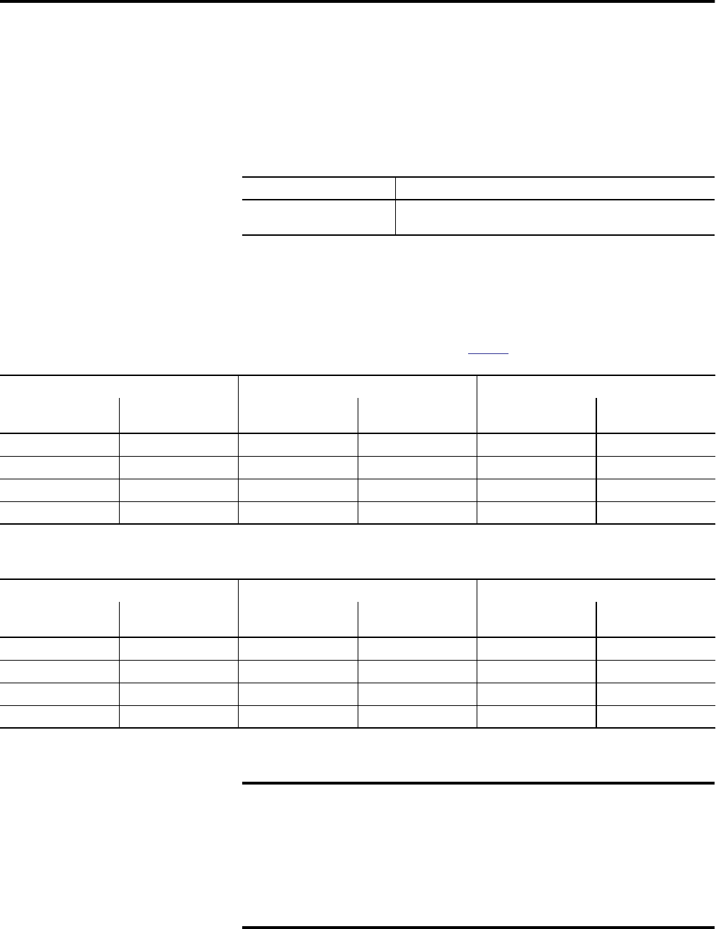
Nom Filter Settings Max Guaranteed Blocked Pulse Width Min Guaranteed Pass Pulse Width
Pulse Width Equivalent
Frequency
(1)
Pulse Width Equivalent
Frequency
(1)
Pulse Width Equivalent
Frequency
(1)
No filter 1 MHz N/A N/A 250 ns 2 MHz
10 µs 50 kHz 7.4 µs 67.5 kHz 25 µs 20 kHz
500 µs 1 kHz 370 µs 1.35 kHz 1.25 ms 400 Hz
5 ms 100 Hz 3.7 ms 135 Hz 12.5 ms 40 Hz
(1) Equivalent frequency assumes a perfect 50% duty cycle and are for reference purposes only. Hence, the no-filter setting is guaranteed to pass 4 MHz even though the
module’s maximum is 1 MHz. This lets the sensor and wiring to attenuate the pulse to 25% duty cycle while the module maintains pulse recognition.
Nom Filter Settings Max Guaranteed Blocked Pulse Width Min Guaranteed Pass Pulse Width
Pulse Width Equivalent
Frequency
(1)
Pulse Width Equivalent
Frequency
(1)
Pulse Width Equivalent
Frequency
(1)
No filter 250 kHz 0.83 µs 600 kHz 2.5 µs 200 kHz
18.5 µs 27 kHz 12.3 µs 40.5 kHz 28.6 µs 17.5 kHz
715 µs 700 Hz 495 µs 1.01 kHz 1.25 ms 400 Hz
7.1 ms 70 Hz 4.95 ms 101 Hz 12.5 ms 40 Hz
(1) Equivalent frequency assumes a perfect 50% duty cycle and are for reference purposes only. Hence, the no-filter setting is guaranteed to pass 4 MHz even though the
module’s maximum is 1 MHz. This lets the sensor and wiring to attenuate the pulse to 25% duty cycle while the module maintains pulse recognition.
IMPORTANT
The built-in filters are simple, averaging, low-pass filters. They are
designed to block noise pulses of width equal to the values presented in
Table Filter Pulse Width and Frequency. Applying full amplitude, 50%
duty cycle signals that are of frequency above the selected filter’s
threshold frequency can result in an average value signal of sufficient
amplitude to turn the input on. A transition from no input to the full
amplitude, 50% duty cycle signal (or back to no signal) can result in
inadvertent input transitions.