
Instruction Manual
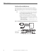
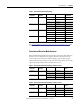
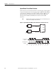
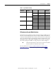
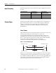
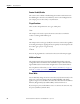
Table Of Contents
- 1769-UM006E-EN-P, Compact High-speed Counter Module User Manual
- Summary of Changes
- Table of Contents
- Preface
- 1 - Module Overview
- 2 - Module Operation
- 3 - Installation and Wiring
- 4 - Module Configuration, Output, and Input Data
- Configure the Module
- Configuration Array
- General Configuration Bits
- Filter Selection
- Program Mode and Program State Run
- Output Program Value (Out0ProgramValue through Out3ProgramValue)
- Output Fault Mode and Output Fault State Run
- Output Fault Value (Out0FaultValue through Out3FaultValue)
- Counter Maximum Count (CtrnMaxCount)
- Counter Minimum Count (CtrnMinCount)
- Counter Preset (CtrnPreset)
- Counter Hysteresis (CtrnHysteresis)
- Counter Scalar (CtrnScalar)
- Cyclic Rate Update Time (CtrnCyclicRateUpdateTime)
- Configuration Flags
- Range High Limit (Range0To11[n].HighLimit) and Range Low Limit (Range0To11[n].LowLimit)
- Range Output Control (Range0To11[n].OutputControl)
- Range Configuration Flags
- Output Array
- Output on Mask (OutputOnMask.0 through OutputOnMask.15)
- Output Off Mask (OutputOffMask.0 through OutputOffMask.15)
- Range Enable (RangeEn.0 through RangeEn.15)
- RBF - Reset Blown Fuse (ResetBlownFuse)
- Control Bits
- Range High Limit or Direct Write Value (Range12To15[n].HiLimOrDirWr)
- Range Low Limit (Range12To15[n].LowLimit)
- Range Output Control (Range12To15[n].OutputControl)
- Range Configuration Flags (12To15)
- Input Array
- Input State (InputStateA0 through InputStateZ1)
- Readback (Readback.0 through Readback.15)
- Status Flags
- Range Active (RangeActive.0 through RangeActive.15)
- Current Count (Ctr[n].CurrentCount)
- Stored Count (Ctr[n].StoredCount)
- Current Rate (Ctr[0].CurrentRate to Ctr[3].CurrentRate)
- Pulse Interval (Ctr[0].PulseInterval and Ctr[1].PulseInterval)
- Status Flags
- 5 - Diagnostics and Troubleshooting
- A - Specifications
- B - Program a 1769-HSC Module, CompactLogix Controller, and 845F Incremental Encoder with RSLogix 5000 Software
- C - Program a 1769-HSC Module, MicroLogix 1500 Controller, and 845F Incremental Encoder with RSLogix 500 Software
- D - Programming Quick Reference
- E - History of Changes
- Glossary
- Index
- Back Cover
28 Rockwell Automation Publication 1769-UM006E-EN-P - July 2013
Chapter 2 Module Operation
Input Frequency
Maximum input frequency is determined by the input configuration as shown in
the table.
Counter Types
Each of the four possible counters can be configured to stop counting and set a
flag at its limits (linear counter) or to rollover and set a flag at its limits (ring
counter). A counter’s limits are programmed by the CtrnMaxCount and
CtrnMinCount words in the module’s configuration array. Both types are
described below.
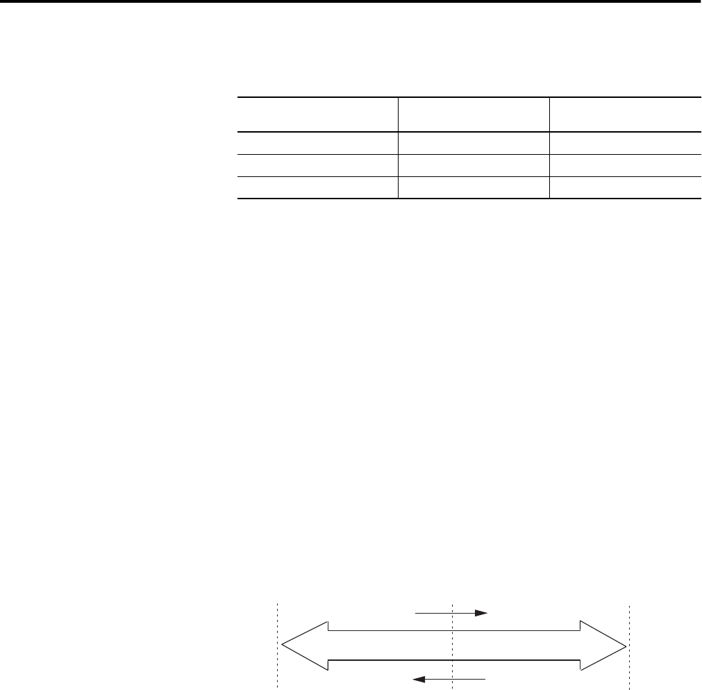
Linear Counter
Figure 7 illustrates linear counter operation. In linear operation, the current count
(Ctr[n].CurrentCount) value remains between, or equal to, the
user-programmed minimum count (CtrnMinCount) and maximum count
(CtrnMaxCount) values. If the Ctr[n].CurrentCount value goes above (>) or
below (<) these values, the counter stops counting, and an overflow/underflow
bit is set. The overflow/underflow bits can be reset using the
CtrnResetCounterOverflow and CtrnResetCounterUnderflow bits.
Figure 7 - Linear Counter Diagram
Pulses are not accumulated in an overflow/underflow state. The counter begins
counting again when pulses are applied in the proper direction. For example, if
you exceed the maximum by 1000 counts, you do not need to apply 1000 counts
in the opposite direction before the counter begins counting down. The first
pulse in the opposite direction decrements the counter.
Input Configuration Input Frequency
1769-HSC Module
Input Frequency
Packaged Controller
X4 Quadrature encoder 250 kHz 250 kHz
X2 Quadrature encoder 500 kHz 250 kHz
All other configurations 1 MHz 250 kHz
Count Up
Count Down
Counter Value
Maximum Count Value
Overflow and Hold
Minimum Count Value
Underflow and Hold
0