
Instruction Manual
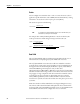
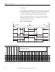
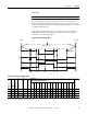
Table Of Contents
- 1769-UM006E-EN-P, Compact High-speed Counter Module User Manual
- Summary of Changes
- Table of Contents
- Preface
- 1 - Module Overview
- 2 - Module Operation
- 3 - Installation and Wiring
- 4 - Module Configuration, Output, and Input Data
- Configure the Module
- Configuration Array
- General Configuration Bits
- Filter Selection
- Program Mode and Program State Run
- Output Program Value (Out0ProgramValue through Out3ProgramValue)
- Output Fault Mode and Output Fault State Run
- Output Fault Value (Out0FaultValue through Out3FaultValue)
- Counter Maximum Count (CtrnMaxCount)
- Counter Minimum Count (CtrnMinCount)
- Counter Preset (CtrnPreset)
- Counter Hysteresis (CtrnHysteresis)
- Counter Scalar (CtrnScalar)
- Cyclic Rate Update Time (CtrnCyclicRateUpdateTime)
- Configuration Flags
- Range High Limit (Range0To11[n].HighLimit) and Range Low Limit (Range0To11[n].LowLimit)
- Range Output Control (Range0To11[n].OutputControl)
- Range Configuration Flags
- Output Array
- Output on Mask (OutputOnMask.0 through OutputOnMask.15)
- Output Off Mask (OutputOffMask.0 through OutputOffMask.15)
- Range Enable (RangeEn.0 through RangeEn.15)
- RBF - Reset Blown Fuse (ResetBlownFuse)
- Control Bits
- Range High Limit or Direct Write Value (Range12To15[n].HiLimOrDirWr)
- Range Low Limit (Range12To15[n].LowLimit)
- Range Output Control (Range12To15[n].OutputControl)
- Range Configuration Flags (12To15)
- Input Array
- Input State (InputStateA0 through InputStateZ1)
- Readback (Readback.0 through Readback.15)
- Status Flags
- Range Active (RangeActive.0 through RangeActive.15)
- Current Count (Ctr[n].CurrentCount)
- Stored Count (Ctr[n].StoredCount)
- Current Rate (Ctr[0].CurrentRate to Ctr[3].CurrentRate)
- Pulse Interval (Ctr[0].PulseInterval and Ctr[1].PulseInterval)
- Status Flags
- 5 - Diagnostics and Troubleshooting
- A - Specifications
- B - Program a 1769-HSC Module, CompactLogix Controller, and 845F Incremental Encoder with RSLogix 5000 Software
- C - Program a 1769-HSC Module, MicroLogix 1500 Controller, and 845F Incremental Encoder with RSLogix 500 Software
- D - Programming Quick Reference
- E - History of Changes
- Glossary
- Index
- Back Cover
32 Rockwell Automation Publication 1769-UM006E-EN-P - July 2013
Chapter 2 Module Operation
Rate/Timer Functionality
To ensure maximum accuracy, the module offers two different methods to
calculate the rate.
• Per Pulse = 1/Pulse Interval
• Cyclic = Number of Pulses/User-defined Time Interval
You select the method used, depending upon the pulse speed as defined below.
These are continuously available regardless of input operational mode.
Pulse Interval Rate Calculation Method
The pulse interval rate method is very accurate for slower rates, that is, when the
pulse interval (or time between pulses) is large compared to the system clock
timer (1 μs). A timer is used to measure the time between two successive pulses.
The inverse of this value is the pulse interval rate. The pulse interval rate cannot
be read directly from the module. It needs to be calculated. The calculation can be
performed in the user control program.
This method is not as accurate for higher pulse rates. When the pulse interval
shrinks, two factors can distort the per pulse calculation. If the pulse interval is
close to the measuring timer’s clock frequency, 1 MHz, the granularity of the time
increments has a greater effect on rate inaccuracy. In addition, the rate can be
calculated many times over the course of a single backplane scan. As a result, the
rate data obtained at a backplane scan is only that of the very last pair of pulses
and disregards the other rate calculations that have occurred during that interval.
This can result in rate inaccuracy if the pulses are unevenly spaced.
Cyclic Rate Calcu
lation Me
thod (current rate)
The module continuously calculates rates for each of its four possible counters,
regardless of operational mode (for example, up/down count). The 32-bit signed
integer rate from each counter is reported in the Ctr[n].CurrentRate words of the
input array.
In this method, the rates are calculated at the end of a counter’s configured cycle
time. This is configured via the CtrnCyclicRateUpdateTime configuration
word/menu. Valid entries are 1…32,767 ms. The number of net counts, net
change in Ctr[n].CurrentCount, during that period is converted into a rate value,
providing an average pulse rate.
IMPORTANT
The Rate/Timer Functionality information does not apply to the
L23E packaged controller.
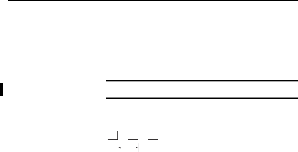
Pulse Interval = 100 µs
Frequency = 1/100 µs = 10,000 Hz