
Instruction Manual
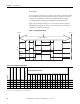
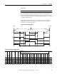
Table Of Contents
- 1769-UM006E-EN-P, Compact High-speed Counter Module User Manual
- Summary of Changes
- Table of Contents
- Preface
- 1 - Module Overview
- 2 - Module Operation
- 3 - Installation and Wiring
- 4 - Module Configuration, Output, and Input Data
- Configure the Module
- Configuration Array
- General Configuration Bits
- Filter Selection
- Program Mode and Program State Run
- Output Program Value (Out0ProgramValue through Out3ProgramValue)
- Output Fault Mode and Output Fault State Run
- Output Fault Value (Out0FaultValue through Out3FaultValue)
- Counter Maximum Count (CtrnMaxCount)
- Counter Minimum Count (CtrnMinCount)
- Counter Preset (CtrnPreset)
- Counter Hysteresis (CtrnHysteresis)
- Counter Scalar (CtrnScalar)
- Cyclic Rate Update Time (CtrnCyclicRateUpdateTime)
- Configuration Flags
- Range High Limit (Range0To11[n].HighLimit) and Range Low Limit (Range0To11[n].LowLimit)
- Range Output Control (Range0To11[n].OutputControl)
- Range Configuration Flags
- Output Array
- Output on Mask (OutputOnMask.0 through OutputOnMask.15)
- Output Off Mask (OutputOffMask.0 through OutputOffMask.15)
- Range Enable (RangeEn.0 through RangeEn.15)
- RBF - Reset Blown Fuse (ResetBlownFuse)
- Control Bits
- Range High Limit or Direct Write Value (Range12To15[n].HiLimOrDirWr)
- Range Low Limit (Range12To15[n].LowLimit)
- Range Output Control (Range12To15[n].OutputControl)
- Range Configuration Flags (12To15)
- Input Array
- Input State (InputStateA0 through InputStateZ1)
- Readback (Readback.0 through Readback.15)
- Status Flags
- Range Active (RangeActive.0 through RangeActive.15)
- Current Count (Ctr[n].CurrentCount)
- Stored Count (Ctr[n].StoredCount)
- Current Rate (Ctr[0].CurrentRate to Ctr[3].CurrentRate)
- Pulse Interval (Ctr[0].PulseInterval and Ctr[1].PulseInterval)
- Status Flags
- 5 - Diagnostics and Troubleshooting
- A - Specifications
- B - Program a 1769-HSC Module, CompactLogix Controller, and 845F Incremental Encoder with RSLogix 5000 Software
- C - Program a 1769-HSC Module, MicroLogix 1500 Controller, and 845F Incremental Encoder with RSLogix 500 Software
- D - Programming Quick Reference
- E - History of Changes
- Glossary
- Index
- Back Cover
36 Rockwell Automation Publication 1769-UM006E-EN-P - July 2013
Chapter 2 Module Operation
Output Control
All 16 outputs can be controlled by any of the four counters or by the user’s
control program, via the output mask function. Output states are determined by
count, rate (not supported in packaged controller), ranges, mask configuration
data, overcurrent status, and safe state settings and conditions.
The 16 outputs are made up of four real (physical) outputs and 12 virtual
outputs. The status of the real and virtual outputs is available to the user
program. The real outputs are electronically protected from overloads.
Masks
You can use an Output On Mask or an Output Off Mask.
Output On Mask
Using the Output On Mask, all of the module’s outputs can be turned on directly
by the user control program, like discrete outputs. A bit that is set in the mask
turns on the corresponding real or virtual output.
Output Off Mask
The Output Off Mask has veto power over any output. It can turn any or all of
the module’s outputs off. When a bit in this mask is set to 0, the output will be
turned off. Each bit is logically ANDed with the Output On Mask and masks of
active and enabled ranges. If the bit in this mask is set to 1, the output can be
turned on or off by the ranges, or the Output On Mask. The final result is
available as the Readback.n bit.
IMPORTANT
To turn outputs on, you must use both the Output On Mask and
the Output Off Mask.